Reznor SFT Unit Installation Manual User Manual
Page 12
Form RZ -NA-I-SFT, Mfg No. 173474 (Rev 6), Page 11
7C
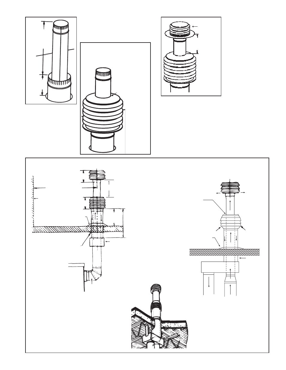
Slide combustion air inlet
over the vent pipe and fasten
to the end of the combustion
air pipe.
Install field-
supplied
flashing at
roof opening.
3. Attach the concentric adapter. Insert the
vent pipe and combustion air pipe up
through the roof and secure the adapter box.
Flash the combustion air pipe to the out-
side of the roof as required.
Seal top joint
(between the vent
pipe and air inlet)
with silicone.
4. Slide the combustion air in-
let over the vent pipe and fas-
ten collar to the end of the com-
bustion air pipe with sheetmetal
screws (See Figure 7C). Seal
joint at top between vent pipe
and combustion air inlet with
silicone sealant to prevent wa-
ter leakage.
9-3/8
(238mm)
6 ft (1829mm) minimum
12 (305mm)
Wall or
Adjoining
Building
11 (279mm)
Flashing
(field
supplied)
Roof
18(457mm)
minimum 5 ft (1524mm)
maximum (Size
according to
anticipated
snow depth.)
Thimble
Concentric
Adapter
Vent Pipe - A minimum of 12
(305mm) of straight pipe is
recommended between the
heater outlet and the elbow.
See No 4, page 7,
for requirements
and use of taper-
type connectors.
7) Connect Concentric Adapter to the Heater - Use the pipe
specified and joints required for type of pipe. If collars at the
heater or the collar or opening on the adapter are different diam-
eters from the pipe (use only diameters listed on page 7), make
joints with field-supplied taper-type reducer or increaser.
A minimum of 12" (305 mm) of straight pipe is required at the
venter outlet.
Due to the high temperature, do not enclose the exhaust pipe or
place pipe closer than 6" (152 mm) to combustible material.
Installation of the vertical vent and combustion air system on your
separated-combustion unit is complete.
Figure 7E - Installation of Separated-Combustion Unit with Vertical Vent and Combustion Air Pipes (Option CC2)
Rear View
Side View
"Through-the-Roof" View of a
typical installation of a vertical vent/
inlet air terminal and concentric
adapter (Option CC2)
Exhaust
Terminal
7D
12" (305mm)
minimum
5. Attach the exhaust ter-
minal with sheetmetal
screws (See Figure 7D).
6. Vertical vent terminal/
combustion air inlet is in-
stalled and ready for con-
nection to the heater.
Refer to Figure7E and
verify that all installation
requirements are met.
Snow
Clearance
7B
22"
(559mm)
minimum
Vent
Termina
l
Flue
Exhaust
(Vent )
Pipe
Seal with high
temperature silicone
rubber sealant supplied
with the kit.
Combustion
Air Inlet
Flashing
(field
supplied)
Roof
Combustion
Air Pipe
Concentric
Adapter
Vent Pipe
(See
requirements
on page 7.)
Combustion
Air Pipe
(See requirements
on page 7.)