Venting and combustion air – Reznor SFT Unit Installation Manual User Manual
Page 7
Form RZ -NA-I-SFT, Page 6
9. Venting and Combustion Air
All separated combustion, power vented units MUST BE equipped with both combustion air and exhaust piping to the outdoors. The unique
concentric adapter assembly required with this heater allows for both combustion air and exhaust piping with only one horizontal or vertical
penetration hole in the building.
Installation should be done by a qualified agency in accordance with these instructions. The qualified service agency installing this separated-
combustion system is responsible for the installation.
The systems illustrated in this manual are the only venting/combustion air systems approved for a Model SFT heater.
Hazards of Chlorine - The presence of chlorine vapors in the combustion air of gas-fired heating equipment presents a potential corrosion hazard.
Chlorine found usually in the form of freon or degreaser vapors, when exposed to flame will precipitate from the compound, and go into solution
with any condensation that is present in the heat exchanger or associated parts. The result is hydrochloric acid which readily attacks all metals
including 300 grade stainless steel. Care should be taken to separate these vapors from the combustion process. This may be done by wise location
of unit vent terminals with regard to exhausters or prevailing wind directions. Remember, chlorine is heavier than air. This fact should be kept in
mind when determining installation location of these heaters and building exhaust systems.
WARNING: Do not use an existing venting system. This heater requires installation of the combustion
air/vent system ordered with the unit (either Option CC2 or Option CC6).
Specific Venting Requirements (read all before installing)
1. Concentric Adapter Kit (ordered with the heater as either Option CC2 or Option CC6)
All Model SFT installations require a concentric adapter kit. Each kit includes the concentric adapter box (See Figure 4), a vent terminal cap, and
an inlet air guard or cap. Follow the instructions on pages 7 - 9 to install a horizontal vent/combustion air system (Option CC6). Follow the
instructions on pages 10 - 11 to install a vertical vent/combustion air system (Option CC2).
The vent/combustion air systems illustrated in Figure 6D or 7E are the only venting/combustion air systems approved for this heater.
2. Type of Pipe (field-supplied)
Vent Pipe - the type of vent pipe required depends on the type of installation.
Type of
COMMERCIAL/INDUSTRIAL (Harmonized ANSI Z83.8-1996
RESIDENTIAL (CSA Requirement 10-96)
Installation
and Canadian Standard CAN/CGA A 2.6-M96) - Applies to all
Applies to Model SFT 45, 60, and 75 ONLY
sizes of Model SFT Heaters
Type of VENT
Use either vent pipe approved for a Category III appliance OR
Vent pipe approved for a Category III
Pipe Required
single-wall, 26-gauge or heavier galvanized (or a material of
appliance is required.
equivalent durability and corrosion resistance) vent pipe.
2 (51mm)
2 (51mm)
6 (152mm)
H
F
E
G
D
C
B
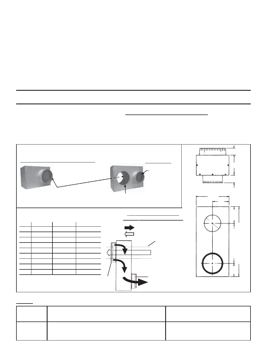
Figure 4A - Concentric Adapter Box Required with all Model SFT Installations
(included in both Option CC2 and Option CC6)
View of Heater Connection Side
Figure 4B - Concentric Adapter Box
Dimensions - inches (mm)
View of Vent Terminal Connection Side
Collar for outside portion of the combustion
air pipe (vent pipe extends through the box
internally concentric to the outside portion
of the combustion air pipe)
Collar for
connecting
indoor portion
of the
combustion air
pipe
Install rubber
seal for vent pipe
Top View of the Concentric
Adapter Box Showing Air Flow
=
Combustion Air Flow
=
Exhaust (Vent) Gas Flow
Side View - Side of the
Adapter Box that
Connects to the Heater
End View
SFT
45-125
150-250
300
A
4 (102)
5 (127)
6 (152)
B
4 (102)
4 (102)
5 (127)
C
3 (76)
4 (102)
4 (102)
D
5-1/2 (140)
7-1/2 (191)
7-1/2 (191)
E
3-1/2 (89)
5 (127)
5 (127)
F
4 (102)
4 (102)
5 (127)
G
12 (305)
16-1/2 (419)
16-1/2 (419)
H
8 (203)
8 (203)
10 (254)
J
6 (152)
6 (152)
8 (203)
Field-supplied vent
pipe passes through
the rubber seal and
extends out both sides
of the concentric
adapter box.
A = Diameter of the
Collar for attaching the
Combustion Air Pipe
from the Heater
J = Diameter of the Collar for
attaching the "Outside" Portion of
the Combustion Air Pipe