Venter motor, Ignition system (cont'd) – Reznor SFT Unit Installation Manual User Manual
Page 21
Form RZ -NA-I-SFT, Page 20
Venter
Wheel
Venter
Motor
Mounting Plate
(Replace mounting
plate gasket if it is
deteriorated or torn.)
A
Figure 15 -
Proper
Position of
the Fan
Blade on the
Motor Shaft
Model Size
Set Screw Torque (In-Lbs)
“A” Hub to Motor
45
80 ± 10
1-1/8"
60, 75, 100, 125
120 ± 10
2"
150, 200
150 ± 10
2"
250, 300
150 ± 10
3-1/4"
24. Venter Motor
Remove dirt and grease from the motor housing. Power venter motor
is permanently lubricated.
The integrated ignition control module controls and monitors opera-
tion of the venter motor. If the contacts fail to close, the venter motor
will not run. If the contacts fail to open, the venter motor will not shut
off, preventing the combustion air pressure switch from opening.
Follow these instructions for replacement of the venter motor (Refer to
Figure 16). Keep all hardware removed to be used in re-assembling
and installing the replacement parts.
1. If the heater is installed, turn off the gas and disconnect the electric
power.
2. Open the access panel. At the burner end, loosen the clamp on the
combustion air flex hose. Let the hose "hang down" so that it is out
of the way of the venter motor.
3. Disconnect the three venter motor wires at their terminal block con-
nections.
4. Holding the motor, remove the screws (3 or 4) that attach the venter
motor mounting plate to the venter housing. Remove the motor and
wheel assembly from the heater.
5. Disassemble the motor and wheel assembly:
(a) With a hex head allen wrench, loosen the venter wheel set screw.
Slide the venter wheel off the shaft.
(b) Remove the four nuts holding the motor mounting plate. Re-
move the mounting plate.
(c) Slid over each bolt is a cylindrical spacer; remove the four spac-
ers.
(d) Loosen the set screw and remove the small fan blade.
6. Re-assemble with the replacement venter motor (NOTE: Check the
gasket on the motor mounting plate; if the gasket is deteriorated or
torn, replace it - Size 45, P/N 155651; Sizes 60-300, P/N 155652):
(a) With the blade side closest to the motor, slide the small fan
blade on to the shaft. Position the blade so that it does not hit
the motor and tighten the set screw to the flat side of the motor
shaft.
(b) Slide the spacers over the bolts. Position the mounting plate
with the side with the gasket away from the motor; secure with
the nuts (hand tighten with a nut driver; do not use a power
tool). Rotate the fan to check for clearance. If required, loosen
the set screw and adjust the position of the fan blade.
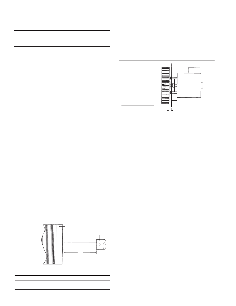
(c) With the "closed" side toward the motor, slide the venter wheel
over the end of the shaft. Position the wheel with the spacing
shown in Figure 16. Tighten the set screw to the flat side of the
motor shaft.
7. Install the assembled venter motor and wheel. Follow the wiring
diagram to connect the venter wires. Re-attach the flex hose and
close the access panel.
8. Restore power to the heater and turn on the gas. Light, following
the instructions on the lighting instruction plate. Check for proper
operation.
IMPORTANT: When re-assembling, the brown ground wire must re-
main attached to the ignitor.
CAUTION: Due to high voltage on the spark wire
and electrode, do not touch when energized. See
Hazard Levels, page 2.
Flame Sensor - Refer to Figure 13 and locate the flame sensor. Dis-
connect the wire; remove the screw and the flame sensor. Clean with
an emery cloth.
Ignition Control - The integrated ignition control module monitors
the operation of the heater including ignition. Do not attempt to disas-
semble the ignition control module. However, each heating season the
lead wires should be checked for insulation deterioration and good
connections.
Proper operation of the direct spark ignition system requires a mini-
mum flame signal of 1.0 microamps as measured by a
microampmeter.
For further information and check out procedure on the direct spark
ignition system, refer to the manufacturer's control operating instruc-
tions supplied with the heater.
23. Fan
Remove dirt and grease from the motor. Remove dirt and grease from
the fan guard and blades. Use care when cleaning the fan blades to
prevent causing misalignment or imbalance. Check that the hub of the
fan blades is secure to the shaft.
Follow these instructions for replacement of the fan guard, fan motor
and/or fan blades.
1. If the heater is installed, turn off the gas and disconnect the electric
power.
2. Open the hinged access door and disconnect the fan motor wires.
3. Remove the assembled parts (the fan guard, the motor and the fan
blade).
4. Disassemble and replace whatever parts are needed and reassemble
using whatever part(s) are being replaced and the original parts.
Be sure the fan blade is in the proper position on the shaft; refer to
the illustration and table in Figure 15.
Position the assembly on the heater. Attach the fan guard.
Rotate the fan blade to check for adequate clearance. If adjustment
is required, loosen the mounting screws, re-position the fan guard,
and tighten the screws. Rotate the fan blade and re-check for ad-
equate clearance. Repeat this procedure until the assembly is posi-
tioned properly.
5. Reconnect the fan motor wires and close the access panel.
6. Restore power to the heater and turn on the gas. Light, following
the instructions on the lighting instruction plate. Check for proper
operation.
Figure 16 - Proper
spacing between
the venter wheel
and the motor
mounting plate
Sizes
A
45-125
5/16"
150-300
23/32"
22. Ignition System (cont'd)
Fan Motor
Fan Hub
A