Reznor Q6SP Unit Installation Manual User Manual
Page 9
9
5. Install the correct thermostat housing to subbase.
6. Refer to thermostat instruction sheet for complete
detailed mounting and operating information.
Defrost cycle timer
The defrost cycle timer controls the time interval of the hot
gas defrost after the defrost sensor closes. It is located in
the lower left corner of the defrost control board on the of
the control panel. Three interval settings are available: 30,
60, and 90 minutes. Time setting selection is dependent
on the climate where the unit is being installed. To set the
cycle timer, place the timing pin on the defrost control
board to the desired time interval post.
notE: All units
are shipped from the factory with the default time setting
of 30 minutes. Longer settings are recommended for drier
climate areas and shorter time intervals are recommended
for moist climate areas.
Defrost control Board
Operational Information
• Terminals
r - rc must have 24±V present between
them in order for the time delay and defrost sequences
to be operational.
• Jumpering the
t2 - DFt test pins will communicate
to the board that the defrost T-stat is closed (if the
compressor is running). The defrost thermostat tells
the board whether a defrost cycle needs to be started
or terminated.
notE: The defrost T-stat is closed at
32° F or below and is open at 68° F or above, but it’s
state is unknown if the temperature is between 32° F
and 68° F.
• With the DFT closed, the unit will run for 30/60/90
minutes in heat mode and then defrost the outdoor
coil. The defrost will turn off the outdoor fan, turn on
the compressor and raise the coil temperature to 68°
F. This will open the DFT and terminate the defrost. If
the DFT does not open the defrost will end after 10
minutes.
• Jumpering the
tEst terminal to the c (common)
terminal (While the compressor is in heat mode), will
over-ride the defrost boarrd and initiate a faster defrost
test in 5, 10 or 15 seconds as determined by the 30, 60
or 90 minute defrost pin settings. (The factory setting
is 30 minutes).
– This will bypass the compressor off delay when the
unit goes into defrost test and if left in defrost test, the
delay will be bypassed when the test is terminated
by the processor.
notE: If the jumper is removed
before the test is over, the processor will perform the
remainder of a normal defrost. See step 2 above.
• The delay/no-delay pin concerns compressor operation
during defrosts. To switch from no-delay to delay, remove
the pin from the
no - delay pin location and shift it to
the
delay pin location. The default setting is delay.
– Reciprocating compressors should only use this
setting in conjunction with an approved hard start
kit.
– Scroll compressors that have noise issues while
going into or coming out of defrost should use this
30 second delay to reduce the defrost noise.
– Manually initiating a defrost will cause the compressor
to run continually when entering defrost.
Normal defrost operation
To test normal defrost operation when the temperature is
above 35° F, jumper
r to DFt on the 624656 board and
allow the unit to run for 30 minutes. Defrost will continue
until the
r to DFt jumper is removed or for 10 minutes.
Remove the jumper.
The 5 minute time delay feature can be shortened 1 time
to 1 second by jumping the
test to c terminal. Remove
the jumper and repeat as desired.
notE: If jumper is left on the test to common pins
permanently, the defrost cycle will become inoperable.
Defrost Test Procedure
1. Jumper
t2 to DFt at the test terminals.
2. With unit running in heat mode, short the
tEst terminal
to the common terminal near it. This will speed up the
board and cause it to enter defrost mode in 5/10/15
seconds depending on the defrost time selection.
Compressor delay will not function during speed-up.
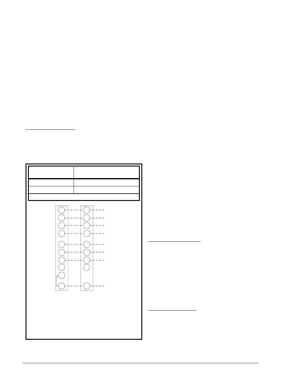
Figure 8. typical connections -
2 stage cool/3 stage Heat t-stat
Y1
Y2
W
1
/E
G
RH
RC
Y1
Y2
W
1
/E
G
R
Indoor Thermostat
Sub-Base
Unit Low Voltage
Terminal
24 V Hot
Stage 3
Heat
(Optional)
Blower
Emer. Heat
Stage 2
Heat/Cool
Stage 1
Heat/Cool
24 V Com
Rev. Valve
B
W2
B
C
O
C
O
W2
‡
t-stat Wire
Gauge
recommended t-stat Wire
length - Ft. (unit to t-stat)
18 Ga.
0 - 60
16 Ga.
61 - 130
Field Supplied Wiring - Use Solid Class II Copper Wire.
‡ “O” - Energized when thermostat system is in “Cool”
Mode.
notE: If thermostat has one combined “O/B” Terminal
and
an Economizer is installed, see Economizer
Installation Instructions for unit wiring change for proper
operation.