Wiring dia gram, Three phase 60 hz – Reznor Q6SP Unit Installation Manual User Manual
Page 19
19
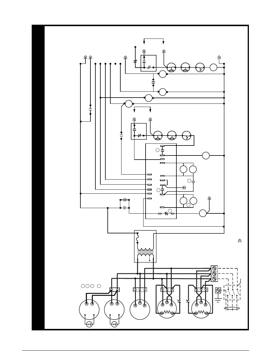
Three Phase 60 Hz.
4.
For suppl
y wire ampacities and o
ver
current pr
otection,
see unit
rating label
.
5.
For
“C”
Series Models onl
y.
For 208V operation remo
ve wire fr
om 230V
tap and place on 208V tap.
1.
Couper le courant
av
ant de faire letretien.
2.
Empl
oy
ez uniquement des conducteu
rs
en cuivre
.
710961
0
0709
WIRING DIA
GRAM
Q6SP Series Con
ver
tible
Pa
ck
ag
ed/Electric Heat Pump 208-230/460
Volt
NO
TES:
1.
Disconnect all po
wer bef
ore servicing.
2.
For suppl
y connections use copper conductor
s onl
y.
3.
If an
y of the original wire as supplied with the furnace
mu
st be replaced,
it
mu
st be replaced with wiring material ha
ving a temperature rating of
at least 105C.
CCH - Crankcase Heater
s,
Stage 1&2 Compressor
CC1&2 - Contacto
r, Stage 1&2 Compressor
IBC - Contactor
, Indoor Bl
ow
er Motor
R
VS - Re
versing
V
alv
e Solenoid
OFC - Contactor
, Outdoor
Fa
n
HPR - Heat Pump Rel
ay
T1
T2
T1
T2
T1
T3
T2
IBC
L1
L2
L3
GND
24V
Common
24V
Ho
t
Compressor 1
T2
T3
T1
CC2
Compressor 2
T2
T1
T3
CC1
Au
x.
Switch
(N.C
.)
CC2
Au
x.
Switch (N.C
.)
CC1
CCH1
CCH2
DF1
DF2
W2
Y
O
E
R
C
C
O
E
W2
R
DFT
Y
DFT
DFT
RV
S
RV
S
T1
T2
OFC
CC1
CC2
Au
x.
Switchs (N.O
.)
HK-4
E-8
1
4
7
HPR
High
Pressure
Switch
Stage
1
Ev
ap
.
Freez
estat
Lo
w
Pressure
Switch
Defrost
Board
E-1
E-2
Y1
Factor
y
Jumper
EHR
3
1
4
2
EHR
HPR
A
B
IBC
BIR
3
1
2
4
BIR
CC1
3
6
9
HPR
High
Pressure
Switch
Stage
2
Ev
ap
.
Freez
estat
Lo
w
Pressure
Switch
E-4
E-5
Y2
Factor
y
Jumper
CC2
6
5
EH
R
LV
T-C (24V COM.)
LV
T-W2 (Stage 3 Heat
)
LV
T-
B
LV
T-
G
HK-3
HK-2
HK-1
E-9
LV
T-W1/E (Emer
. Heat)
LV
T-O (Re
v.
Va
lv
e-Cool)
LV
T-Y1 (Stage 1 Heat/Cool)
LV
T-
R
LV
T-
Y2
(Stage 2 Heat/Cool)
Au
x.
Switc
h
(N.O
.)
IBC
Field Supplied Disconnect
(3Phase
Po
wer Only
)
F
or supply connections use
copper conductors only
.
Unit
Te
rminal
Bloc
k
Tr
ansf
or
mer
24V Sec.
Primar
y
Outdoor
Fa
n Motor
Outdoor
Fa
n Motor
Indoor
Fa
n Motor
LVT - Lo
w
V
oltage
Te
rminal
DFT - Defrost
Ther
mostat
BIR - Blo
wer Isolation Rel
ay
EHR - Electr
ic Heat Rela
y
HK - Heater Kit
E - Economiz
er
- Indicates plug connection
.
Letter Indicates which plug.
Number indicates pin location.
4 Amp
Circuit
Break
er
See Note
5
1
OFC
Defrost Board Rel
ay
Operation:
Closes dur
ing defrost.
Rating
: 1 A Maximu
m
Opens dur
ing defrost
. Rating
: 1/2 HP at 230
VA
C Maximum
Closed when
“Y”
is energiz
ed.
Open when
“Y”
is deenergiz
ed.
Pro
vides
“Off
” dela
y time of 5 min when
“Y”
is deenergi
ze
d.
With DFT closed and
“Y”
energiz
ed, compressor r
un time is
accumulated
. Opening of DFT du
ring defrost or inte
rv
al per
iod
resets the inte
rv
al to 0.
1
4
3
2
2
3
4
1
¢710961&¤
Figure 11. ladder Diagram for Q6sP-090/120 (c/D) series