Warning, Unit installation – Reznor Q6SP Unit Installation Manual User Manual
Page 4
4
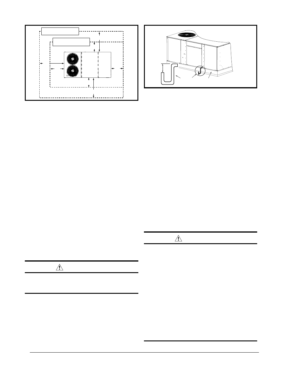
Roof Curb
Condensate
Drain
3"
Min.
Figure 2. condensate Drain
The electric unit is suitable for installation on combustible
flooring or class A, B, or C roofing materials. A clearance
of at least 36 inches to combustibles from all sides of the
unit is required.
Where accessibility to combustibles
clearances are greater than minimum unit clearances,
accessibility clearances must take preference.
Sufficient clearance for unobstructed airflow through the
outdoor coil must be maintained in order to achieve rated
performance. See Figure 1 for minimum recommended
clearances to obstructions.
thermostat
A 2 stage heating / cooling 24VAC heat pump thermostat
is required for these units.
notE: If “optional” electric
heat is added a 3 Stage Heat / 2 Stage Cool 24VAC
electric heat pump thermostat must be used.
air Filter requirements
A suitable air filter must be installed in the unit or in the
return air system. Refer to Specification & Electrical Data
Table for recommended filter sizes. Air filter pressure drop
must not exceed 0.08 inches WC. Replacement filters
should be of like kind and size, rated for 500 ft per minute.
This unit is supplied with air filters. Air filter(s) must be
installed ahead of the evaporator coil of this unit. All
return air to this unit must pass through the filters before
entering this unit.
WarnInG:
never operate unit without a filter. a failure to
follow this warning could result in a fire, personal
injury, or death.
condensate Drain
Condensate is removed from the unit through the 3/4”
(19mm) PVC pipe located on the front side of the unit. Install
a 3” (8cm) Min. trap between the drain line and an open
vent of the same size for proper condensate removal. (See
Figure 2) Refer to local codes and restrictions for proper
condensate disposal requirements. When connecting
rigid drain line, hold any fittings with a wrench to prevent
twisting.
Do not overtighten!
Figure 1. Minimum clearances to combustibles
Top of unit
to be
unobstr
ucted
Recommended Clearances
for Servicibility
Minimum Required
Clearances to Combustibles
36"
36"
36"
36"
48"
60"
48"
unIt InstallatIon
Minimum clearance requirements
Units are certified as combination Heating and Cooling
equipment for outdoor installation only at the minimum
clearances to combustible materials shown. Clearances
shown (Figure 1) are for both Downflow and Horizontal
discharge.
Packaging removal
1. Remove top crate brackets and wooden cap assembly
from top of unit (Figure 3, page 5).
2. Remove lower crate brackets, 4 side skids, and 2 end
skids from each side of unit.
Do not remove base
rails from unit.
3. Rig unit and raise up approximately 4 feet off the ground.
(Also see Rigging & Hoisting on page 5).
4. Remove crate brackets (Figure 4, page 5) securing
long and short bottom boards to underside of unit.
notE: Some screws are located in fork slots.
5. Remove long & short bottom boards from beneath unit.
6. Inspect unit thoroughly for shipping damage.
7. Carefully lower and position unit to it’s permanent
location.
rigging & Hoisting
WarnInG:
to avoid the risk of property damage, personal
injury, or death, it is the rigger’s responsibility
to ensure that whatever means are used to hoist
the unit are safe and adequate:
•
the lifting equipment must be adequate for the
load. see table 1 (page 16) for unit weights.
•
the unit must be lifted from the holes in the
base rails using cables or chains as shown in
Figure 5.
•
spreader bars (Figure 5) are required to protect
the unit and ensure even loading.
•
Keep the unit in an upright position at all times.
the rigging must be located outside the units
center of gravity. refer to Physical Data Pages
(table 1) for center of gravity location.
• All panels must be securely in place during
rigging and hoisting.