Warning – Reznor Q6SP Unit Installation Manual User Manual
Page 8
8
This unit must be electrically grounded in accordance
with local codes or, in the absence of local codes, with
the National Electrical Code (ANSI/NFPA 70) or the CSA
C22.1 Electrical Code. Use the grounding lug provided in
the element access compartment for grounding the unit.
Blower speed
The blower speed is preset at the factory. For optimum
system performance and comfort, it may be necessary to
change the factory set speed. Refer to Blower Performance
Data (Tables 5 - 8, pages 22 - 25) for the allowable operating
range and adjustments. Units are shipped from the factory
with the blower drive belt removed and located in the same
compartment as the field electrical connections.
WarnInG:
to avoid personal injury or property damage,
make certain that the motor leads cannot
come into contact with any uninsulated metal
components of the unit.
To change the blower speed:
1. Disconnect all electrical power to the unit and remove
the blower access panel.
2. Loosen the motor tension bars to allow removal of the
blower belt from the motor sheave.
3. Loosen top set screw on motor sheave and turn
clockwise to close (increases blower speed), or
counterclockwise to open (decreases blower speed).
4. Replace belt on pulleys and position motor mounting
plate to correct position for proper belt tension.
5. Tighten tension bar bolts.
Check all factory wiring per the unit wiring diagram and
inspect the factory wiring connections to ensure none
loosened during shipping or installation.
Low Voltage Connections - Thermostat
A two stage heating/two stage cooling 24 VAC heat pump
thermostat is required for these units.
notE: If “optional”
electric heat is added, a 3 stage Heat / 2 stage cool
24 VAC heat pump thermostat must be used. Several
options are available for a room thermostat depending
on the accessories installed with the unit. Select a
thermostat which operates in conjunction with the installed
accessories. The thermostat should be mounted about
five feet above the floor on an inside wall. The thermostat
should be kept away from drafts, slamming doors, lamps,
direct sunlight and supply air flow.
To install the thermostat:
1. Position the subbase on an inside wall and mark the
mounting holes and thermostat cable openings.
2. Cut out the cable opening and route the thermostat
cable from the unit’s low voltage compartment to the
thermostat location. The thermostat cable is supplied by
the installer. For recommended wire sizes, see Figure
8 (page 9).
3. Connect the cable leads to the subbase or thermostat
terminals and to the unit’s low voltage terminal block
as shown in Figure 8. System wiring diagrams are also
provided on the inside of the control access panel and
in Figures 11 & 12 (page 19 & 20).
4. Secure the subbase or thermostat to the wall using
screws provided with the thermostat.
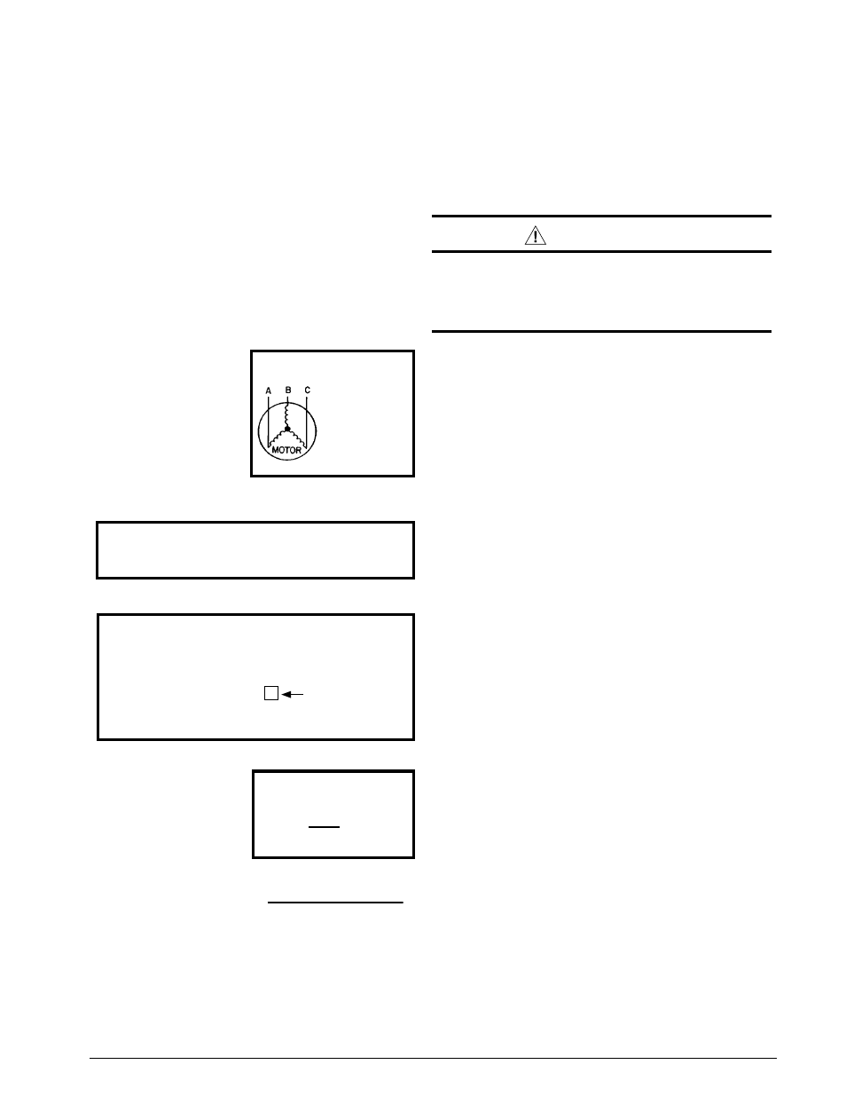
Example
:
AB = 451V
BC = 460V
AC = 453V
2. Determine the average voltage in the power supply.
3. Determine the maximum deviation:
4. Determine percent of
voltage imbalance by
using the results from
steps 2 & 3 in the following
equation.
max voltage deviation
from average voltage
= 100 x
average voltage
% Voltage Imbalance
6
454
100 x
= 1.32%
Example:
1. Measure the line voltages
of your 3 phase power
supply where it enters the
building and at a location
that will only be dedicated
to the unit installation (at
the units circuit protection
or disconnect).
Unbalanced 3-Phase Supply Voltage
Voltage unbalance occurs when the voltages of all phases
of a 3-phase power supply are no longer equal. This
unbalance reduces motor efficiency and performance.
Some underlying causes of voltage unbalance may include:
Lack of symmetry in transmission lines, large single-phase
loads, and unbalanced or overloaded transformers. A
motor should never be operated when a phase imbalance
in supply is greater than 2%.
Perform the following steps
to determine the percentage of voltage imbalance:
In this example, the measured line voltages were
451, 460, and 453. The average would be 454 volts
(451 + 460 + 453 = 1,364 / 3 = 454).
The amount of phase imbalance (1.32%) is satisfactory
since the amount is lower than the maximum allowable
2%. Please contact your local electric utility company if
your voltage imbalance is more than 2%.
Example:
From the values given in step 1, the BC voltage
(460V) is the greatest difference in value from
the average:
460 - 454 = 6
454 - 451 = 3
454 - 453 = 1
Highest Value