Vertical terminal instructions - option cc2 – Reznor SDH Option - Installation - Venting Instructions User Manual
Page 9
Form I-SDH-V, P/N 211410 R5, Page 9
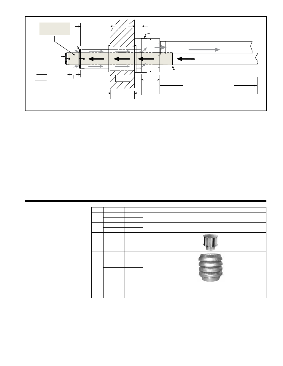
1 (25mm)
Minimum
48 (1219mm)
Maximum
Concentric
Adapter
Box Wid
th
Wall
Exhaust
Grill
Inlet Air
Guard
Combustion Air to Heater (seal joints)
Vent (Flue Exhaust) Pipe
from heater (seal joints)
Heater
Distance between the
Concentric Adapter Box
and the Heater
For Maximum Length, see TABLE 1 on page 2.
Minimum length is 3 ft (.9M).
Attach one-piece terminal end pipe to vent
run no more than 6 (152mm) from the box.
Attach box to wall with brackets.
One-piece
Terminal End
Vent Pipe
Minimum
4 (102mm)
Maximum
16 (406mm)
6
(152
mm)
Minimum
3 (76mm)
Maximum
6 (152mm)
2 (51mm) if wall is combustible
Top
View
b) Install terminal-end vent pipe. Being sure the vent
pipe is in the proper flow direction, slide the end through
the box.
Position the vent pipe so that it will extend between 3”
(76mm) and 6” (152mm) past the end of the combustion
air pipe and no more than 6” (152mm) out of the box
toward the heater. No more than 6” (152mm) from the
box, connect the terminal-end vent pipe to the vent run.
8. Position the exhaust grill over the end of the vent
pipe. See FIGURE 12. Attach the grill to the end of the
vent pipe with the four 1/2” long screws in the kit.
9. Seal the vent pipe to the concentric adapter box.
Verify that the terminal-end section of vent pipe has a
slight downward drop (1/4” per foot/6mm per 305mm)
toward the outside. Use silicone sealant and seal the
circumference of the pipe and the opening of the box.
Seal the area around the pipe completely.
10. Attach the indoor combustion air pipe. Use
sheetmetal screws to attach the single-wall combustion
air pipe run to the collar on the concentric adapter box.
Seal with tape or sealant. If installing a Model SDH Size
150, field-supplied taper-type 5” to 6” (127mm to 152mm)
reducer is required to connect the combustion air pipe to
the collar on the box. See
FIGURE 8, page 6.
Installation of the horizontal vent and combustion air sys-
tem on your separated-combustion unit is complete.
Verify
compliance with all venting installation requirements,
pages 2-6, and FIGURE 12.
TABLE 6 - Parts in the
Vertical Vent Terminal/
Combustion Air
Package (Option CC2)
Components Required -
Factory and Field
VERTICAL
TERMINAL
INSTRUCTIONS -
Option CC2
Field-supplied
installation
requirements:
• Vent pipes - see requirements, page 2
• Combustion air pipes - see requirements, page 2
• Taper-type pipe diameter reducers and/or increasers as required
• Thimble (a thimble is not required if wall is of non-combustible construction)
• Flashing
• Sheetmetal screws, tape, and sealant as required
Before beginning, verify that the kit is at the site and that all components are correct for
the installation. Be sure all required field-supplied parts are available.
Qty
Sizes
P/N
Description
1
75-125
205895 Complete Vertical Vent/Combustion Air Terminal Kit (Same as
Option CC2)
150-400A 205896
1
75-125
205884 Concentric Adapter Box Assy (NOTE: Refer to
FIGURE 5, page
5, and verify diameter of vent pipe opening.)
150-400A 205885
1
75-125
110051 Exhaust (Vent)
Terminal Assembly
150-400A 110052
1
75-125
155635
Combustion Air
Inlet Assembly
150-400A 53330
2
75-400A 207232 Brackets for attaching Concentric Adapter Box (See FIGURE 13,
page 10.)
1
75-400A
53335 Tube of High Temperature Silicone Sealant