Warning – Reznor SDH Option - Installation - Venting Instructions User Manual
Page 7
Form I-SDH-V, P/N 211410 R5, Page 7
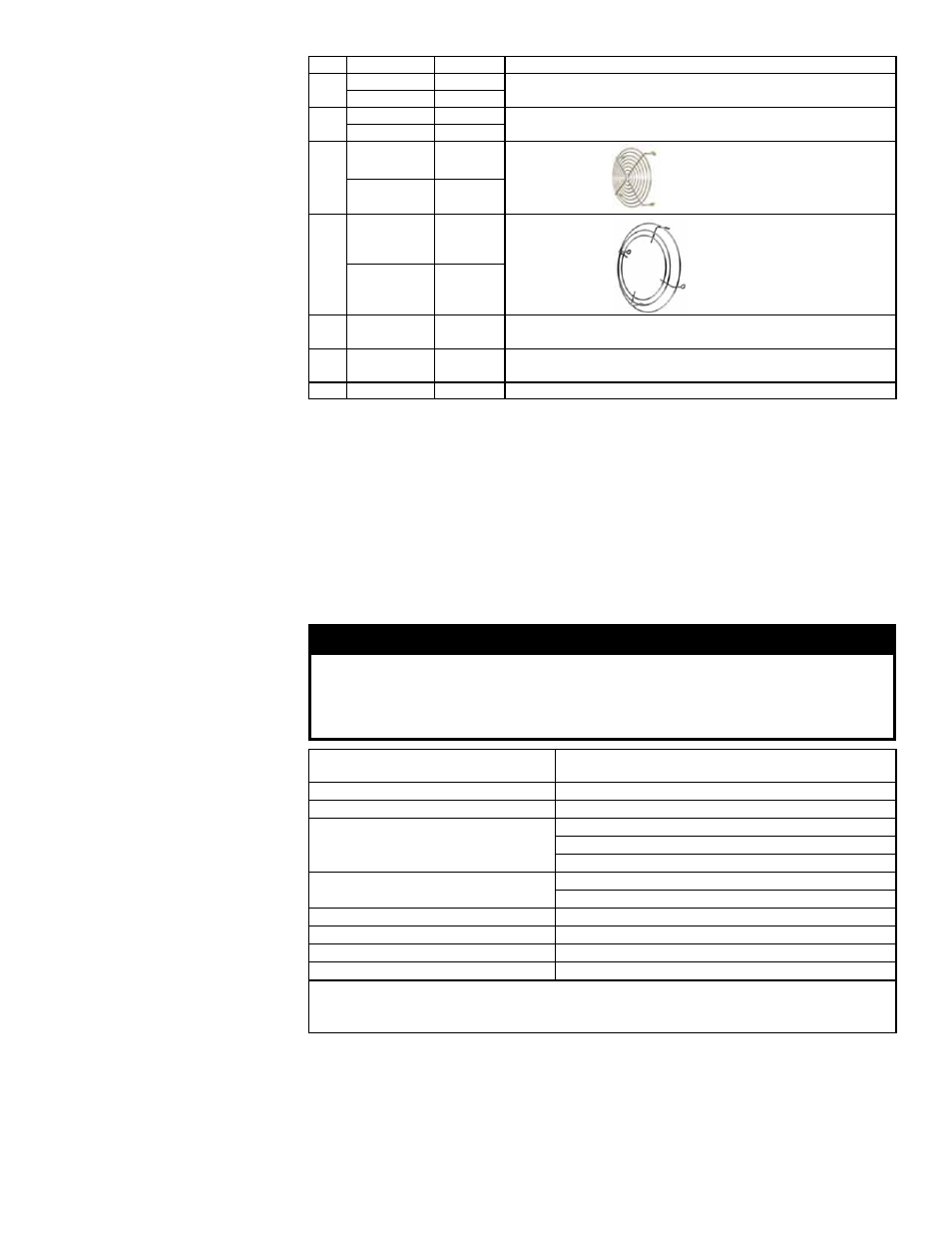
TABLE 4 - Parts in
the Horizontal Vent/
Combustion Air
Terminal Package
(Option CC6)
Qty Sizes
P/N
Description
1
75-125
211762 Complete Horizontal Vent/Combustion Air Terminal Kit (Same
as Option CC6)
150-400A
211763
1
75-125
211789 Concentric Adapter Box (NOTE: Refer to
FIGURE 5, page 5,
and verify diameter of vent pipe opening.)
150-400A
211790
1
75-125
211791
Exhaust Grill
150-400A
211792
1
75-125
151755
Inlet Guard
150-400A
124940
8
75-400A
37661
#10-16 x 1/2" long Screws to attach the exhaust grill and the
inlet guard
2
75-400A
207232 Brackets for attaching Concentric Adapter Box (See FIGURE
11, page 8.)
1
75-400A
53335
Tube of High Temperature (450°F) Silicone Sealant
Installation Instructions
for Horizontal Kit
Option CC6
(in compliance with
requirements on
pages 2-6)
1. Determine the location on the outside wall for the vent terminal. Location
must comply with vent length requirements, Requirement No. 2 on page 2. In most
applications, the terminal would be on a level with the heater mounting height. Allow
1/4” per foot (6mm per 305mm) downward pitch for condensate drain.
Minimum clearances for the horizontal vent terminal are shown in
TABLE 5. Also,
select a location that complies with adjoining building clearances as shown in
FIGURE 12, pages 8-9.
Products of combustion can cause discoloring of some building finishes and
deterioration of masonry materials. Applying a clear silicone sealant that is normally
used to protect concrete driveways can protect masonry materials. If discoloration is
an esthetic problem, re-locate the vent or install a vertical vent.
WARNING
All vent terminals must be positioned or located away from fresh air intakes,
doors and windows to preclude combustion products from entering occupied
space. Failure to comply could result in severe personal injury or death and/
or property damage.
TABLE 5 - Clearances
to Horizontal Vent
Terminal
Structure
Minimum Clearances for Vent Terminal Location (all
directions unless specified)
Forced air inlet within 10 ft (3.1M)*
3 ft (0.9M) above
Combustion air inlet of another appliance
6 ft (1.8M)
Door, window, or gravity air inlet (any build-
ing opening)
4 ft (1.2M) horizontally
4 ft (1.2M) below
1 ft (305mm) above
Electric meter, gas meter ** and relief
equipment
U.S. - 4 ft (1.2M) horizontally
Canada - 6 ft (1.8M)
Gas regulator **
3 ft (0.9M) horizontally
Adjoining building or parapet
6 ft (1.8M)
Adjacent public walkways
7 ft (2.1M) above
Grade (ground level)
3 ft (0.9M) above***
*Does not apply to the inlet of a direct vent appliance. **Do not terminate the vent directly
above a gas meter or service regulator. *** Consider local snow depth conditions. The vent
must be at least 6” (152mm) higher than anticipated snow depth.
2. Install the Vent Pipe and Combustion Air Pipe Runs - Use the type of pipe
specified in Requirement No. 1, page 2. Comply with Requirement No. 3, pages 2-3,
when attaching pipes to the heater. Length must comply with Requirement 2, page 2.
Seal all joints. Due to the high temperature,
do not enclose the exhaust pipe or place
pipe closer than 6” (152 mm) to combustible material. Extend the runs close to the
wall location selected in Step 1 and comply with Requirement No. 6, page 4.