Reznor SDH Option - Installation - Venting Instructions User Manual
Page 3
Form I-SDH-V, P/N 211410 R5, Page 3
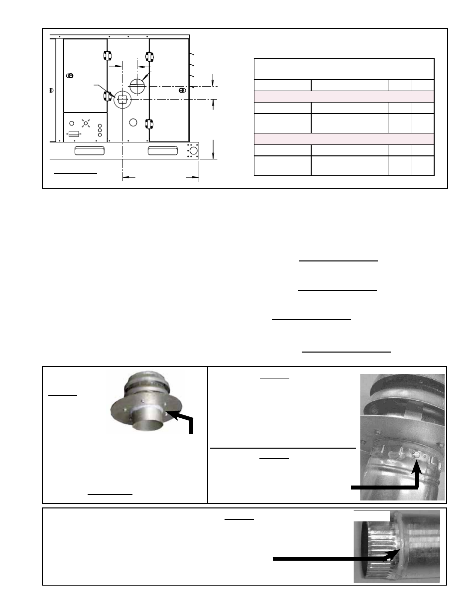
Combustion
Air Inlet
Collar
Venter
Outlet
Sizes 75-150
16-13/16 (427mm)
Sizes 175-400A
17-1/4 (438mm)
Sizes 75-150
20-3/4 (527mm)
Sizes 175-400A
31 (787mm)
Y
X
FIGURE 1 - Locations of Outlet and Inlet Connections
Side View
Location of Inlet Combustion Air Collar (in relation
to vent pipe connection)
Cabinet Sizes
Model SDH Sizes
X
Y
Dimensions (inches)
A, B
75, 100, 125, 150
4
3-5/8
C, D, E
175, 200, 225, 250,
300, 350, 400A
5
4
Dimensions (mm)
A, B
75, 100, 125, 150
102
92
C, D, E
175, 200, 225, 250,
300, 350, 400A
127
102
Provide pipes as specified in
Requirement No. 1, page 2, and seal joints as follows:
• To join sections of Category III pipe, follow the pipe manufacturer’s instructions
for joining and sealing.
• To join sections of single-wall pipe (vent pipe or combustion air pipe), secure
slip-fit pipe connections using sheetmetal screws or rivets. Seal all joints with
aluminum tape or silicone sealant.
• When joining the terminal section of double-wall vent pipe (vertical vent
terminal Option CC2 only) to the vent cap, follow the illustrated step-by-step
instructions in
FIGURE 2.
When joining the terminal section of double-wall vent pipe (vertical vent
terminal Option CC2 only) to the single-wall or Category III vent pipe run,
follow the illustrated step-by-step instructions in
FIGURE 3.
When joining two sections of double-wall vent pipe (vertical vent terminal
only; restrictions apply), follow the pipe manufacturer’s instructions for joining
and sealing vent pipe sections.
4. Joints and Sealing
NOTE: Joints connecting
double-wall pipe apply
only to a vertical vent
terminal (Option CC2
Vertical Vent/Combustion
Air Kit). Horizontal vent
does not require double
wall pipe; see Type of
Pipe requirement on
page 2.
FIGURE 2 - Follow STEPS to join Double-Wall (Type B) Pipe and the Vent Terminal Cap (applies only
to vertical vent/combustion air kit Option CC2)
FIGURE 2 -
STEP 1
Place a continual 3/8” bead of silicone
sealant around the circumference of the vent
cap collar. This will prevent any water inside
the vent cap from running down the double-
wall pipe.
Do STEP 2 immediately following STEP 1.
FIGURE 2 - STEP 2
Insert the collar on the vent cap inside the
inner wall of the double-wall pipe. Insert
as far as possible. Add additional silicone
sealant to fully close any gaps between
the vent cap and the double wall pipe.
This is necessary to prevent water from
entering the double-wall pipe.
Secure the vent cap to the double-wall
pipe by drilling and inserting a 3/4” long
sheetmetal screw into the vent cap
collar. Do not overtighten screw.
FIGURE 2 - STEP 3
FIGURE 3 - Follow STEPS
to join Double-Wall (Type
B) Pipe (VERTICAL
VENT Option CC2 ONLY)
to Single-Wall Pipe, to
Category III Pipe, or to a
Taper-type Connector
FIGURE 3 - STEP 1
On the single-wall pipe, Category III pipe,
or taper-type connector, place a continual
1/4” bead of silicone sealant around the
circumference.
Do STEP 2 (next page) immediately
following STEP 1.
Single-Wall Vent Pipe