Reznor SDH Option - Installation - Venting Instructions User Manual
Page 12
Form I-SDH-V, P/N 211410 R5, Page 12
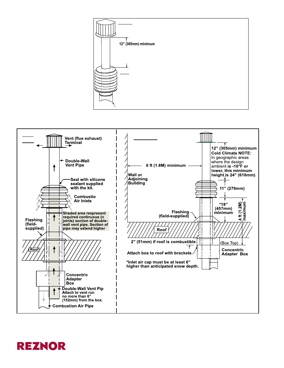
FIGURE 16 - Add
Section of Double-
Wall Pipe if needed;
Install Combustion Air
Inlet; and Attach Vent
Terminal
www.ReznorHVAC.com; (800) 695-1901
©2014 Reznor LLC, All rights reserved.
Trademark Note: Reznor
®
, T
CORE
2
®
and PREEVA
®
are registered in at least the United States.
All other trademarks are the property of their respective owners.
07/14 (Serial No. Dated Code BNG) Form I-SDH-V (Version .5)
Installation of the vertical vent and combustion air system on your separated-combus-
tion unit is complete.
Verify compliance with all venting installation requirements,
pages 2-6, and FIGURE 17 below.
FIGURE 17 - Installation
of Unit with Vertical
Vent Terminal/
Combustion Air Inlet
(Option CC2)
Rear
View
Side View
VERTICAL TERMINAL
INSTRUCTIONS -
Option CC2 (cont’d)
®
SECOND, Install the Exhaust (Vent) Terminal.
Follow the instructions in FIGURE 2, page 3.
FIRST, Install Combustion Air Inlet.
1) Slide the combustion air inlet over the vent pipe.
2) Fasten bottom of inlet to the combustion air pipe
with sheetmetal screws. Be sure not to penetrate
the vent pipe.
3) At the top, completely seal the space between the
vent pipe and the air inlet with silicone.
Double-wall V
ent Pipe
Cold Climate NOTE: In geographic
areas where the design ambient is
-10°F or lower, this minimum height
is 24” (610 mm)
Single-wall Combustion Air Pipe