Reznor SDH Option - Installation - Venting Instructions User Manual
Page 8
Form I-SDH-V, P/N 211410 R5, Page 8
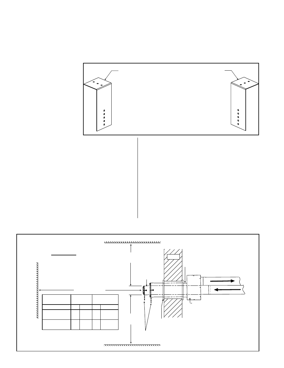
FIGURE 11 - Brackets
for Attaching the
Concentric Adapter Box
to the Wall
1) Attach the Brackets to the Box - The 6 (152mm)
portion of each bracket is designed with five 7/32
diameter holes so that attachment to the box can
be adjusted.
If the wall is combustible, position brackets to allow for a 2
(51mm) clearance between the box and the wall. Adjust
bracket attachment to allow for the slight downward pitch of
the terminal vent pipe.
After careful positioning, use sheetmetal screws to attach the
brackets. NOTE: If any holes are made in the box in error,
they must be sealed.
2) Attach the Box to the Wall (Step 5)
When the box is attached to the wall in Step 5, use
the 2-1/2 (64mm) portion of the brackets. To adjust to
construction each bracket has three 7/32 diameter holes.
HORIZONTAL
TERMINAL
INSTRUCTIONS -
Option CC6 (cont’d)
Secure Concentric Adapter
Box to wall with brackets.
Adjust so that the box has a
slight downward slope to the
outside.
One-piece
Terminal End
Vent Pipe -
Pitch to
Drain
Thimble
Combustion Air Pipe
- Pitch to Drain
Y
Minimum
3 ft (1M)
Minimum
X - Minimum*
Adjoining Building
Building Projection
Building Overhang - Maximum 24 (610mm)
Wall
Rain water should drain out
and not roll into the pipes.
Side View
FIGURE 12 - Installation of a Typical Separated-Combustion Unit with Horizontal Vent Terminal and
Combustion Air Pipe (Option CC6)
Model SDH
Sizes
X*
Y
75, 100
4 ft 1.2 M 18" 457 mm
125, 150,
175, 200, 225 4 ft 1.2 M 24" 610 mm
250, 300,
350, 400A
6 ft 1.8 M 36" 914 mm
*Minimum - Check for and comply with
local Codes.
Installation Instructions
for Horizontal Kit
Option CC6 (cont’d)
(in compliance with
requirements on
pages 2-6)
3. Prepare a clearance hole through the outside wall for the combustion air
pipe -- a 6” (152mm) diameter pipe for Sizes 75-125 or an 8” (203mm) diameter
pipe for Sizes 150-400A. Outside wall construction thickness should be 1” (25mm)
minimum and 48” (1219 maximum). The larger diameter combustion air pipe serves
as clearance for the vent pipe on non-combustible construction. A thimble may be
required depending on wall construction and/or local codes.
4. Prepare the Concentric Adapter Box
a) Attach the brackets to the box. Follow the instructions in FIGURE 11.
b) Attach the outside portion of the combustion air
pipe to the box. Determine the length by measuring the
bracket length from box to wall, plus the wall thickness,
plus 4-16” (102-406 mm) beyond the wall. (The inlet air
pipe should extend beyond the outside wall a minimum of
4” (102mm) to a maximum or 16” (406mm).
Attach the inlet air pipe to the collar of the concentric
adapter with sheetmetal screws and seal.
5. Attach the concentric adapter box to the wall. Insert
the combustion air pipe out through the wall.
Attach the
brackets to the wall (
FIGURE 11). On the outside, caulk
or flash the inlet air pipe. Flashing is field-supplied.
6. On the outside, position the inlet guard over the
end of the combustion air pipe. See
FIGURE 12. Attach
the guard to the inlet air pipe with the four 1/2” long
screws provided.
7. Determine length and install the “terminal-end”
vent pipe.
a) Determine length of pipe. The length of the
continuous piece of terminal-end vent pipe is determined
by the installation within the maximum and minimum
requirements. See
FIGURE 12 to determine lengths of
each segment and calculate the total length required. The
“terminal-end” vent pipe extending through the box and
concentric through the inlet air pipe
must be one piece
of vent pipe without joints. The connection to the vent
pipe run, must be a maximum of 6” (152mm) from the
heater side of the box.