Venting requirements (cont’d) – Reznor SDH Option - Installation - Venting Instructions User Manual
Page 4
Form I-SDH-V, P/N 211410 R5, Page 4
Venting
Requirements
(cont’d)
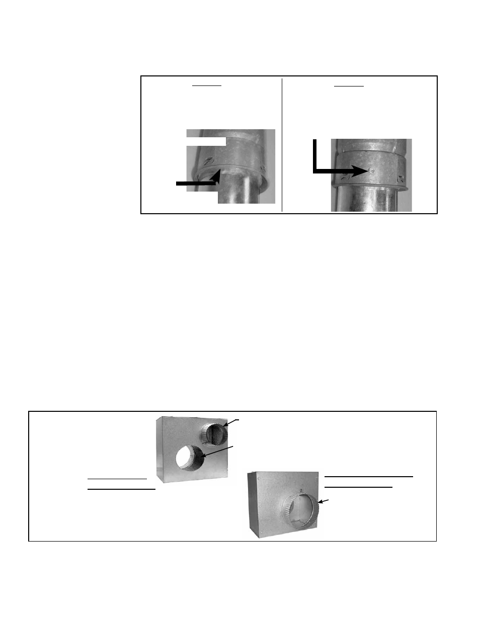
FIGURE 3 - STEP 2
Insert the pipe prepared with sealant
into the inner pipe of the double-wall
pipe until the bead of sealant contacts
the inner pipe creating a sealed joint.
FIGURE 3 - STEP 3
Spaced equally around the double-wall
pipe, drill three small holes below the
sealant ring. Insert 3/4 inch long sheet-
metal screws to secure the joint. Do not
overtighten screws.
Single-Wall with
Sealant (STEP 1)
Double-Wall Pipe
6. Clearance
Do not enclose the vent pipe or place pipe closer than 6” (152mm) to combustible
material.
5. Support
Support horizontal run every six feet (1.8M). Support vertical run of Category III vent
pipe in accordance with the requirements of the pipe manufacturer. Support vertical
single-wall pipe in accordance with accepted industry practices. Do not rely on the
heater or the adapter box for support of either horizontal or vertical pipes. Use non-
combustible supports on vent pipe.
NOTE: The vertical vent double-wall vent terminal pipe does not attach to the concen-
tric adapter box and must be supported during installation.
All separated combustion installations
require a concentric adapter box as illustrated
in
FIGURE 4. The concentric adapter box is included in the vent/combustion air ter-
minal kit. Installation instructions depend on whether the vent terminal is horizontal
(Option CC6) or vertical (Option CC2).
8. Concentric Adapter
Box
FIGURE 4 - A Concentric
Adapter Box is a Required
Part of all Model SDH
Installations
Collar for attaching
outside concentric
portion of the
combustion air pipe
A vent/combustion air kit which includes the concentric
adapter box is ordered with the heater. A horizontal
terminal vent/combustion air kit is Option CC6; a
vertical terminal vent/combustion air kit is Option CC2.
Collar for connecting indoor portion of the
combustion air pipe
Opening for exhaust vent pipe to pass through
the box. (See NOTE in FIGURE 5.)
View of Vent Terminal
Connection Side
On all Model Sizes, any length of single-wall vent pipe exposed to cold air or run
through an unheated area or an area with an ambient temperature of 45°F or less must
be insulated along its entire length with a minimum of 1/2” foil-faced fiberglass, 1-1/2#
density insulation.
Where extreme conditions are anticipated, install a means of condensate disposal.
7. Condensation
The illustrations in
FIGURE 5 and FIGURE 6 apply to the concentric adapter box in
both the horizontal terminal vent/combustion air kit (Option CC6) and the vertical ter-
minal vent/combustion air kit (Option CC2). All dimensions are the same except for the
opening for the vent pipe (See
NOTE in FIGURE 5).
Instructions for Attaching the Terminal-End Double-Wall (Type -B)
Section of the VERTICAL Vent Pipe (Applies only to Option CC2
installation) (cont’d)
4. Joints and Sealing (cont’d)
View of Heater
Connection Side
FIGURE 3 (cont’d) -
Follow STEPS to join
Double-Wall (Type B)
Pipe (VERTICAL VENT
Option CC2 ONLY) to
Single-Wall Pipe, to
Category III Pipe, or to
a Taper-type Connector