Warning – Reznor SDH Option - Installation - Venting Instructions User Manual
Page 10
Form I-SDH-V, P/N 211410 R5, Page 10
1. Determine the location of the vent terminal.
Select a location away from fresh air intakes, allowing space for the concentric
adapter box inside. Vent terminal must be located from adjacent buildings as shown
in
FIGURE 17, page 12.
TABLE 7 - Minimum
Spacing Required for
More Than One Vertical
Vent/Combustion Air
Terminal (Option CC2)
2. Install the Vent Pipe and Combustion Air Pipe Run - Use the type of
pipe specified in Requirement No. 1, page 2, and comply with the attachment
requirements in Requirement No. 3, pages 2-3. Length must comply with
Requirement No. 2, page 2.
Seal all joints. Due to the high temperature,
do not enclose the exhaust pipe or place
pipe closer than 6” (152 mm) to combustible material. Provide supports for the pipes.
Extend the runs to close to the roof at the location selected in Step 1.
3. Prepare a clearance hole through the roof for the combustion air pipe -- a 6”
(152mm) diameter pipe for Sizes 75-125 or an 8” (203mm) diameter pipe for Sizes
150-400A. A thimble may or may not be required depending on building construction
and/or local codes. The larger diameter combustion air pipe serves as clearance for
the vent pipe on non-combustible construction.
4. Prepare the Concentric Adapter Box
a) Attach the brackets to the box. Follow the instructions in FIGURE 13.
Minimum Outdoor Design
Temperature
Minimum Spacing between Centerlines of Vent Pipes in
Vertical Combustion Air/Vent Terminals (Option CC2)
°F
°C
inches
mm
31 or warmer
0 or warmer
36
914
-10 to 30
-23 to -1
60
1524
less than -10
less than -23
84
2134
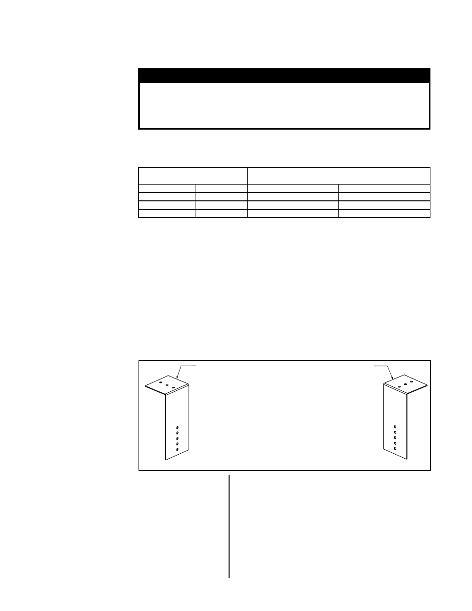
FIGURE 13 - Brackets
for Attaching the
Concentric Adapter Box
to the Roof
1) Attach the Brackets to the Box - The 6 (152mm)
portion of each bracket is designed with five 7/32
diameter holes so that attachment to the box can
be adjusted.
If the roof is combustible, position brackets to allow for a
2 (51mm) clearance between the box and the roof. After
careful positioning, use sheetmetal screws to attach the
brackets. NOTE: If any holes are made in the box in error,
they must be sealed.
2) Attach the Box to the Roof (Step 5)
When the box is attached to the roof in Step 5, use
the 2-1/2 (64mm) portion of the brackets. To adjust to
construction each bracket has three 7/32 diameter holes.
b). Attach the outside portion of the combustion
air pipe to the box. Determine the length of the
combustion air pipe so that dimension ”X” in
FIGURE 14
is equal to the bracket length, plus the roof thickness,
plus anticipated snow depth, but does not exceed 48”
(1219mm) or have less than 18” (457mm) of pipe above
the roof. Attach the inlet air pipe to the collar of the
concentric adapter box with sheetmetal screws.
5. Attach the concentric adapter box to the roof. On
the inside, insert the combustion air pipe up through the
opening and attach brackets to the roof. (See
FIGURES
13, 14, and 15.) On the outside, flash the combustion air
pipe to the roof. Flashing is field supplied
.
6. Determine the length and install the double-wall
vent pipe.
a) Determine minimum length of the continuous
section of double -wall vent pipe (no joints). See
FIGURE 14. The vent pipe extending through the box
and concentric through the inlet air pipe and at least 3”
(76mm) higher
must be one piece of double-wall vent
pipe with no joints.
WARNING
All vent terminals must be positioned or located away from fresh
air intakes, doors and windows to preclude combustion products
from entering occupied space. Failure to comply could result in
severe personal injury or death and/or property damage
.
If more than one vertical concentric vent/combustion air terminal (Option CC2) is being
installed, the minimum spacing between vent centerlines is determined by the mini-
mum outdoor design temperature.
Installation Instructions
for Vertical Vent/
Combustion Air
Terminal Kit Option
CC2 (in compliance with
requirements, pages 2-6)
VERTICAL TERMINAL
INSTRUCTIONS -
Option CC2 (cont’d)