0 vertical vent instructions - option cc2 (cont’d) – Reznor UDBS Option - Installation - Separated Combustion Venting User Manual
Page 14
Form I-UD-V-SC, PN195676R17, Page 14
6) Determine the length and install the double-wall vent pipe.
a. Determine minimum length of the continuous section of double-wall vent
pipe. See FIGURE 15. The vent pipe extending through the box and the inlet air
pipe
must be one piece of double-wall vent pipe without joints.
Determine the minimum length by adding the requirements. Starting at the bottom,
the maximum the vent pipe can extend below the box is 6” (152mm);
plus 6”
(152mm) through the box;
plus length of bracket extending above the box; plus
the width of the roof;
plus the height of the outside combustion air pipe above the
roof;
plus a minimum of 3” (76mm) beyond the top of the inlet air pipe. Total is the
minimum length of the vent pipe section. If the actual piece of vent pipe is longer,
extend it further above the combustion air pipe. Do not extend it more than 6”
(152mm) below the box.
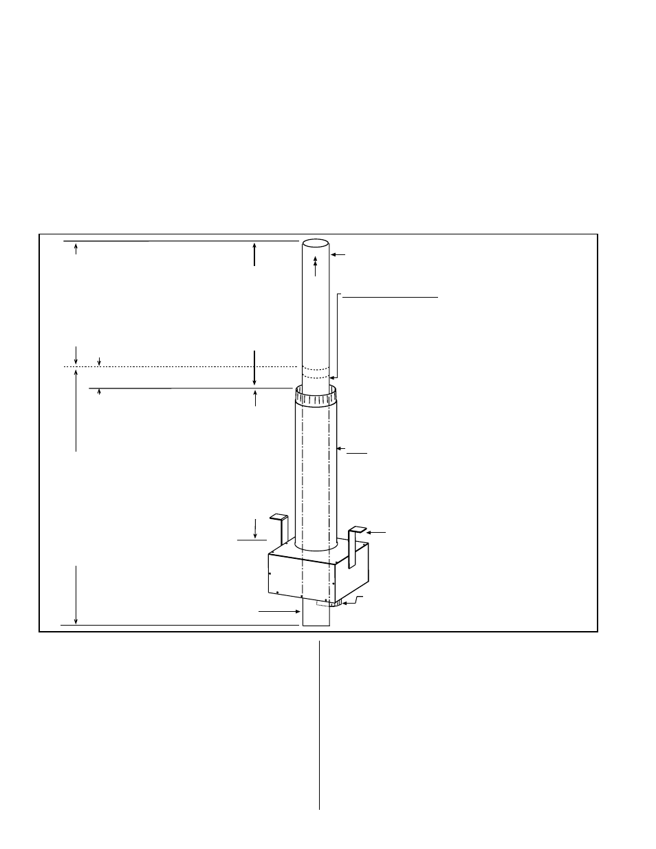
FIGURE 15 -
Concentric Adapter
Box, Outdoor
Combustion Air Pipe,
and Concentric Vent
Pipe
Concentric
Adapter Box
Mounting Brackets
X = length of
combustion air pipe required
through and above the roof.
Height from box to top of inlet air
pipe must not exceed 48 (1219mm).
Minimum height above the roof is
18 (457mm) and must be higher
than anticipated snow depth.
First, attach Combustion Air Pipe and install the
Concentric Box
1) Determine length (X) of pipe (see requirements
on the left).
2) Attach the pipe to the collar on the box.
3) Attach the brackets to the roof.
V
ent Flow
22 (559mm) minimum
Cold Climate NOTE:
In geographic areas where
the design ambient is -10°F
or lower, this minimum
height is 34 (864mm).
Collar for Indoor Portion of
the Combustion Air Pipe
Terminal Vent Pipe -
Extend length of vent
pipe a maximum of 6
(152mm) below the box.
After box is installed, install Concentric Vent Pipe -
One piece of continuous double-wall pipe must
extend from a minimum of 3 (76mm) above the
outer combustion air pipe to a maximum of 6
(152mm) below the box. (NOTE: Vent pipe does not
attach to the box; it must be supported.)
1) Calculate height (see requirements on the left).
2) Be sure vent flow marking on the pipe is in the right
direction.
3) Slide pipe through the box and the outer inlet air pipe.
4) Attach to vent run no more than 6 (152mm) from the
adapter box. See instructions in FIGURE 3, page 5.
Vent pipe
extending
through the
box and the
combustion
air pipe MUST
be one continuous
piece of double-
wall vent pipe.
A second section
of double-wall pipe
is permitted, joining
the long continuous
piece of vent pipe a
minimum of 3 (76mm)
above the top of the
combustion air pipe.
3 (76mm)
minimum
If needed, add a second section of double-wall pipe to
comply with the height requirement on the left.
Terminal V
ent Pipe
(See requirement
s, p
age 3.)
b. Install the vent terminal pipe.
Being sure the pipe is in the proper flow direction, slide
the end into the box and out through the combustion
air pipe. Position the vent pipe so that the end is no
more than 6” (152mm) below the box. The upper
end should extend at least 3” (76mm) above the
combustion air pipe.
NOTE: The vent pipe does
not attach to the box. The installer must provide
support.
Follow the instructions in
FIGURE 3, page 5, for
connecting a double-wall pipe to a single-wall pipe or
taper-type connector.
Seal the circumference of the pipe and the opening of
the box with silicone sealant. Seal the area around the
pipe completely.
7) On the outside, if an additional section of vent pipe is
needed (See
FIGURE 16), add it. Make joint according
to the pipe manufacturer’s requirements. When vent
pipe is the required height,
slide the combustion
air inlet over the vent pipe and fasten the collar to
the combustion air pipe with sheetmetal screws. See
FIGURE 16. Seal the opening at the top between the
vent pipe and the combustion air inlet with silicone
sealant to prevent water leakage.
8) Attach the exhaust (vent) cap. Follow the illustrated
instructions in
FIGURE 2, page 5.
3.0 VERTICAL VENT INSTRUCTIONS - Option CC2 (cont’d)
3.2 Installation Instructions for Vertical Vent/Combustion Air Kit Option CC2 (cont’
d)