2 installation instructions for horizontal, Vent/combustion air kit option cc6, Warning – Reznor UDBS Option - Installation - Separated Combustion Venting User Manual
Page 10
Form I-UD-V-SC, PN195676R17, Page 10
1) Determine the location on the outside wall for the vent terminal. Location must
comply with vent length requirements, Requirement No. 1.3 on page 4. In most
applications, the terminal would be on a level with the heater mounting height.
Allow 1/4” per foot (6mm per 305mm) downward pitch for condensate drain.
Minimum clearances for the horizontal vent terminal are shown in
TABLE 5. Also,
select a location that complies with adjoining building clearances as shown in
FIGURE 12, pages 11- 12.
Products of combustion can cause discoloring of some building finishes and
deterioration of masonry materials. Applying a clear silicone sealant that is
normally used to protect concrete driveways can protect masonry materials. If
discoloration is an esthetic problem, re-locate the vent or install a vertical vent.
Before beginning, verify that the kit is at the site and that all components are correct for
the installation. Be sure all required field-supplied parts are available.
WARNING
All vent terminals must be positioned or located away from fresh air intakes, doors
and windows to preclude combustion products from entering occupied space.
Failure to comply could result in severe personal injury or death and/or property
damage.
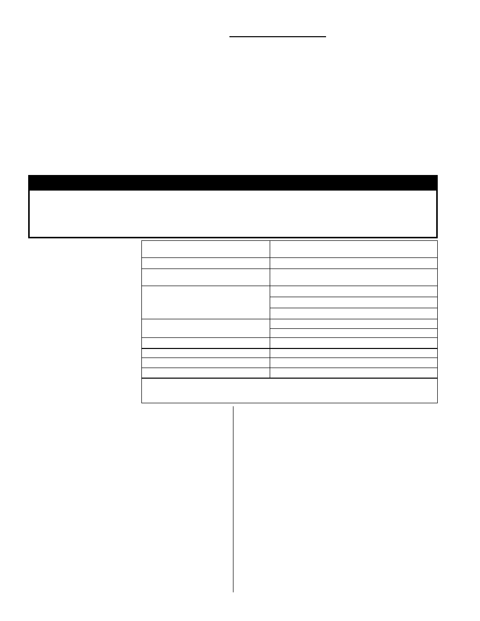
TABLE 5 - Clearances
to Horizontal Vent
Terminal
Structure
Minimum Clearances for Vent Terminal
Location (all directions unless specified)
Forced air inlet within 10 ft (3.1M)* 3 ft (0.9M) above
Combustion air inlet of another
appliance
6 ft (1.8M)
Door, window, or gravity air inlet
(any building opening)
4 ft (1.2M) horizontally
4 ft (1.2M) below
1 ft (305mm) above
Electric meter, gas meter ** and
relief equipment
U.S. - 4 ft (1.2M) horizontally
Canada - 6 ft (1.8M)
Gas regulator **
3 ft (0.9M) horizontally
Adjoining building or parapet
6 ft (1.8M)
Adjacent public walkways
7 ft (2.1M) above
Grade (ground level)
3 ft (0.9M) above***
*Does not apply to the inlet of a direct vent appliance. **Do not terminate the vent directly
above a gas meter or service regulator. *** Consider local snow depth conditions. The vent
must be at least 6” (152mm) higher than anticipated snow depth.
2) Install the Vent Pipe and Combustion Air Pipe Runs
- Use the type of pipe specified in Requirement No.
1.1, page 3. Comply with requirements in Requirement
No. 1.2, page 3, when attaching pipes to the heater.
Length must comply with Requirement 1.3, page 4.
Seal all joints. Due to the high temperature, do not
enclose the vent (exhaust) pipe or place pipe closer
than 6” (152 mm) to combustible material. Extend
the runs close to the wall location selected in Step
1). Support pipes as required in Requirement No.
1.5, page 5. Comply with requirements concerning
condensation in Paragraph 1.7.
3) Prepare a clearance hole through the outside wall
for the combustion air pipe -- a 6” (152mm) diameter
pipe for Sizes 30-125 or an 8” (203mm) diameter
pipe for Sizes 150-400. Outside wall construction
thickness should be 1” (25mm) minimum and 48”
(1219 maximum). The larger diameter combustion air
pipe serves as clearance for the vent pipe on non-
combustible construction. A thimble may be required
depending on wall construction and/or local codes.
4) Prepare the Concentric Adapter Box
a. Attach the brackets to the box. Follow the instructions
in
FIGURE 11.
b. Attach the outside portion of the combustion air
pipe to the box. Determine the length by measuring
the bracket length from box to wall, plus the wall
thickness, plus 4-16” (102-406 mm) beyond the wall.
(The inlet air pipe should extend beyond the outside
wall a minimum of 4” (102mm) to a maximum or 16”
(406mm).
Attach the inlet air pipe to the collar of the concentric
adapter with sheetmetal screws and seal.
5) Attach the concentric adapter box to the wall.
Insert the combustion air pipe out through the wall.
Attach the brackets (
FIGURE 11) to the wall. On the
outside, caulk or flash the inlet air pipe. Flashing is
field-supplied.
2.2 Installation
Instructions
for Horizontal
Vent/Combustion
Air Kit Option
CC6
(in compliance with
requirements on
pages 3-8)
2.0 HORIZONTAL VENT INSTRUCTIONS - Option CC6 (cont’d)