Reznor UDBS Option - Installation - Separated Combustion Venting User Manual
Page 11
Form I-UD-V-SC, PN195676R17, Page 11
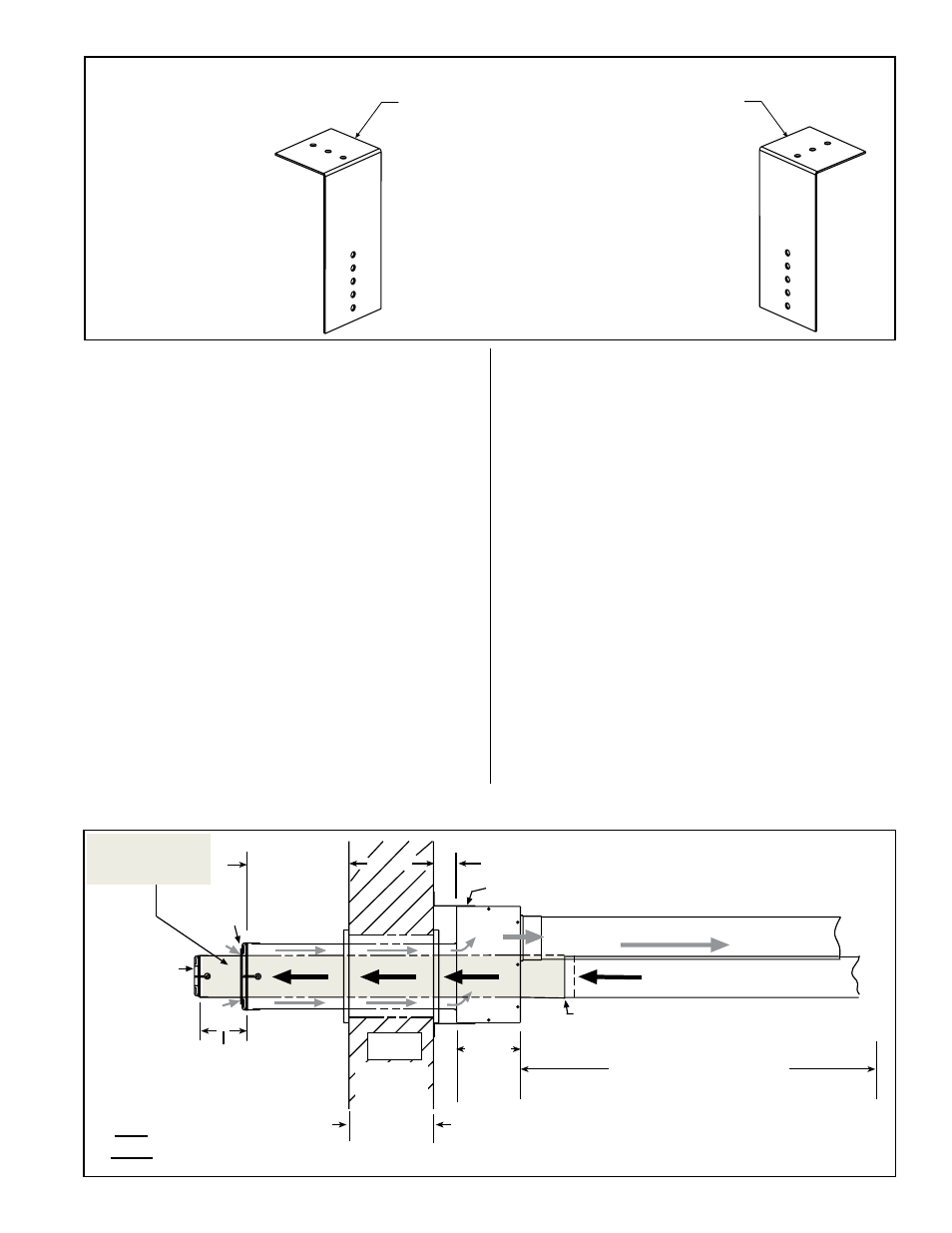
FIGURE 11 -
Brackets for
Attaching the
Concentric
Adapter Box
to the Wall
1) Attach the Brackets to the Box - The 6 (152mm)
portion of each bracket is designed with five 7/32
diameter holes so that attachment to the box can
be adjusted.
If the wall is combustible, position brackets to allow for
a 2 (51mm) clearance between the box and the wall.
Adjust bracket attachment to allow for the slight
downward pitch of the terminal vent pipe.
After careful positioning, use sheetmetal screws to
attach the brackets. NOTE: If any holes are made in
the box in error, they must be sealed.
2) Attach the Box to the Wall (Step 5)
When the box is attached to the wall in Step 5, use the
2-1/2 (64mm) portion of the brackets. To adjust to
construction each bracket has three 7/32 diameter holes.
6) On the outside, position the inlet air guard over the
end of the combustion air pipe. See
FIGURE 12, below
and next page. Attach the guard to the inlet air pipe
with the four 1/2” long screws provided.
7) Determine length and install the “terminal-end”
vent pipe.
a. Determine length of pipe. The length of the
continuous piece of terminal-end vent pipe is
determined by the installation within the maximum
and minimum requirements. See
FIGURE 12 to
determine lengths of each segment and calculate the
total length required. The “terminal-end” vent pipe
extending through the box and concentric through the
inlet air pipe
must be one piece of vent pipe without
joints. The connection to the vent pipe run, must be
a maximum of 6” (152mm) from the heater side of the
box.
b. Install terminal-end vent pipe. Being sure the vent
pipe is in the proper flow direction, slide the end
through the box. Position the vent pipe so that it will
extend between 3” (76mm) and 6” (152mm) past the
end of the combustion air pipe and no more than 6”
(152mm) out of the box toward the heater.
No more than 6” (152mm) from the box, connect the
terminal-end vent pipe to the vent pipe run from the
heater.
8) Position the exhaust grill over the end of the vent
pipe. See FIGURE 12, Top View. Attach the grill to the
end of the vent pipe with the four 1/2” long screws in
the kit.
9) Seal the vent pipe to the concentric adapter box.
Verify that the terminal-end section of vent pipe has a
slight downward drop (1/4” per foot/6mm per 305mm)
toward the outside. Use silicone sealant and seal the
circumference of the pipe and the opening of the box.
Seal the area around the pipe completely.
10) Attach the indoor combustion air pipe. Use
sheetmetal screws to attach the single-wall
combustion air pipe run to the collar on the concentric
adapter box. Seal with tape or sealant.
NOTE: If using 3” combustion air pipe on Size 30,
45, or 60, install a taper-type reducer as illustrated in
FIGURE 7, page 7.
Review Paragraph 1.7 concerning condensation;
comply with all requirements that apply.
FIGURE 12 - Installation of a Typical Separated-Combustion Unit with Horizontal Vent
Terminal and Combustion Air Pipe (Option CC6) - continued on page 12
Concentric
Adapter
Box Wid
th
Wall
Exhaust
Grill
Inlet Air
Guard
Combustion Air to Heater (seal joints)
Vent (Flue Exhaust) Pipe
from heater (seal joints)
Heater
Distance between the
Concentric Adapter Box
and the Heater
For Maximum Length, see TABLE 2 on page 4.
Minimum length is 1 ft (.3M) for Sizes 30-75.
Minimum length is 3 ft (.9M) for Sizes 150-400.
Attach one-piece terminal end pipe to
vent run no more than 6 (152mm) from
the box.
Attach box to wall with brackets.
One-piece
Terminal End
Vent Pipe
Minimum
4 (102mm)
Maximum
16 (406mm)
6
(152
mm)
1 (25mm) Minimum
48 (1219mm)
Maximum
Minimum
3 (76mm)
Maximum
6 (152mm)
2 (51mm) if wall is combustible
Top
View