0 suspending the unit -9, 0 suspending the unit, Unit weight and allowable mounting angle – Reznor RIHVL Unit Installation Manual User Manual
Page 7: Model rihn 30 is not available in canada, See allowable mounting angles in paragraph 5
CODE
in
FIGURE
2
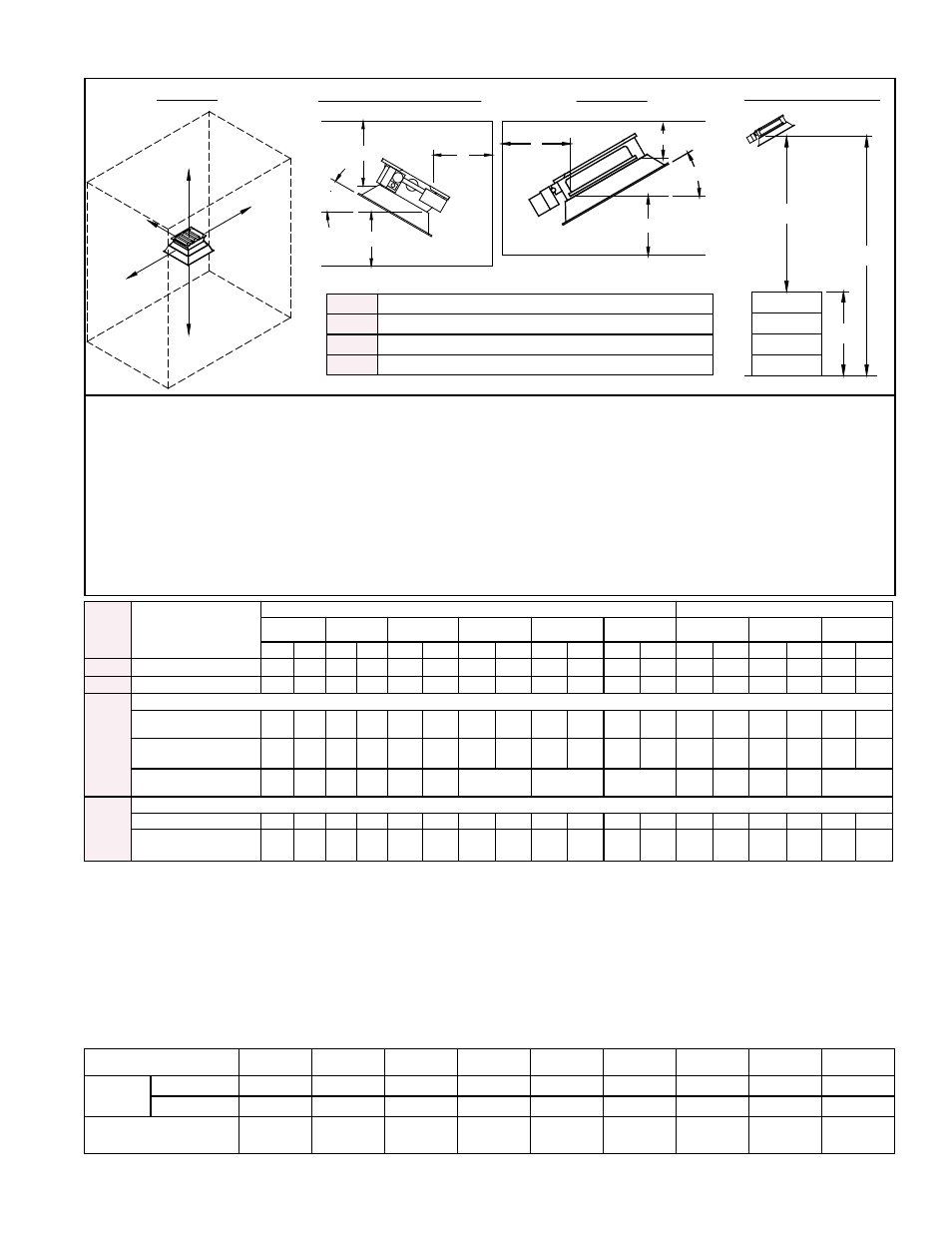
Clearance to
Combustibles
Natural Gas Models
Propane Models
RIHN 30
X
RIHN 60
Y
RIHVN 100
Z
RIHVN 150 RIHVN 160
Z
RIHVN 200
RIHL 50
Z
RIHVL 90
Z
RIHVL 120
Z
inches
mm
inches
mm
inches
mm
inches
mm
inches
mm
inches
mm
inches
mm
inches
mm
inches
mm
A
Side of Heater
30
762
30
762
36
914
46
1168
48
1219
48
1219
30
762
36
914
46
1168
B
Back of Heater
30
762
30
762
30
762
33
838
33
838
33
838
30
762
30
762
33
838
C
Top of Heater:
Mounted 5-29° (no heat
deflector)
60 1524 60 1524
62
1575
64
1626
68
1727
68
1727
60
1524
62
1575
64
1635
Mounted 30° only (no
heat deflector)
48 1219 48 1219
50
1270
58
1473
68
1727
68
1727
48
1219
50
1270
58
1473
Mounted 5-30° with Heat
Deflector, Option DO2
34
864
34
864
38
965
N/A
N/A
N/A
34
864
38
965
N/A
D
Below the Heater:
Standard Reflector
80 2032 80 2032 105 2667
125
3175
140
3556
140
3556
80
2032
105
2667 125 3175
With Parabolic Reflector,
Option DM2
110 2794 110 2794 135 3429
165
4191
180
4572
180
4572
110
2794
135
3429 165 4191
FIGURE 2 - Clearances to Combustibles (Inches and mm)
NOTES:
X
Model RIHN 30 is not available in Canada.
Y
Model RIHN 60 in Canada requires addition of a wire grid,
Option DN2.
Z
See allowable mounting angles in Paragraph 5.
B
A
A
C
D
B
D
C
E
E
B
D
C
3D VIEW
ALL Sizes
STACKING HEIGHT
• In locations used for the storage of combustible materials, signs shall be posted to specify the maximum permissible
stacking height to maintain required clearances from the heater to combustibles. (ANSI Z233.1/NFPA 54)
• The stated clearance to combustibles represents a surface temperature of 90°F (50°C) above room temperature.
Building materials with low heat tolerance (such as plastic, vinyl siding, canvas, tri-ply, etc.) may be subject to
degradation at lower temperatures. It is the responsibility of the installer to assure that adjacent materials are
protected from degradation (ANSI Z83.19).
• It is recommended more distance than the minimum clearance be maintained above the unit whether or not the
construction is combustible to reduce and/or eliminate hot spots and possible staining of painted ceiling surfaces.
• If the unit must be close to the roof or ceiling, interpose a non-combustible baffle (twice the size of the reflector)
between the unit and the roof or ceiling. Allow at least 2” (5cm) between the roof or ceiling and the non-combustible
baffle. Allow at least 12” (31cm) between the non-combustible baffle and the top of the heater.
D
H
M
Sizes 30, 50, & 60 ONLY
A - D See Table below.
E
Mounting Angle (5 - 30°)
H
Stacking Height (equals M-D)
M
Mounting Height (See table on page 4.)
5.0 Suspending
the Unit
Unit Weight and Allowable Mounting Angle
Before installing the unit, check the supporting structure to determine that it has suf-
ficient load-carrying capacity to support the weight.
Mounting angle must be within the tolerance allowed.
Model
RIHN 30
RIHL 50
RIHN 60
RIHVL 90 RIHVN 100 RIHVL 120 RIHVN 150 RIHVN 160 RIHVN 200
Net Wt -
lbs (kg)
Single-Stage
24 (11)
24 (11)
24 (11)
34 (16)
34 (16)
44 (20)
44 (20)
56 (26)
56 (26)
Two-Stage
--
--
--
42 (19)
42 (19)
53 (23)
53 (23)
66 (29.9)
66 (29.9)
Allowable Mounting
Angle Tolerance
5° - 30°
5° - 30°
5° - 30°
5° - 30°
5° - 30°
5° - 30°
5° - 30°
5° - 30°
5° - 30°
P/N 131793R10, Page 7