2 electrical requirements by voltage, And control types, Heater 1 heater 2 – Reznor RIHVL Unit Installation Manual User Manual
Page 11
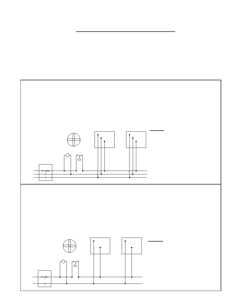
FIGURE 6A - With 120 VAC DIRECT SPARK IGNITION (DSI) SINGLE-STAGE CONTROLS
• Electrical supply: 120 VAC - 60 Hz - 1 Phase.
• Maximum total heater current draw: 0.14 Amps.
• Total heater power consumed: 16.8 VA (16.8W).
• 3-wire field service required.
• Field wiring having a minimum temperature rating of at least 302°F (150°C) shall be used and supply circuit
wiring shall have a minimum size of 16 AWG (1.0mm2).
FIGURE 6B - With 24 VAC DIRECT SPARK IGNITION (DSI) SINGLE-STAGE CONTROLS
• Electrical supply: 24 VAC - 60 Hz or 50 Hz - 1 Phase.
• Maximum total heater current draw: 0.66 Amps.
• Total heater power consumed: 15.9 VA (15.9W).
• 2-wire field service required.
• Field wiring having a minimum temperature rating of at least 302°F (150°C) shall be used and supply circuit
wiring shall have a minimum size of 16 AWG (1.0mm2).
GND
(-)
(+120)
GGS
BK
BK
GGS
VR*
SW*
MV*
W
W
120 VAC DSI HEATER ELECTRICAL SUPPLY AND THERMOSTAT WIRING*
LEGEND
(+120) = 120 VAC Supply Voltage
(-
(-) = Supply Neutral
GND = Earth Ground
MV* = Mechanical Ventilation*
VR* = Ventilation Relay*
SW* = Ventilation Interlock Switch*
(normally opened)
GGS = Green Ground Screw
(inside control box)
W = White Wire – Neutral
BK = Black Wire – 120 VAC call for heat
Thermostat
Heater 1
Heater 2
GND
(+24)
GGS
BL
BL
GGS
VR*
SW*
MV*
24 VAC DSI SINGLE-STAGE HEATER ELECTRICAL SUPPLY AND THERMOSTAT WIRING*
LEGEND
(+24) = 24 VAC Supply Voltage
GND = Earth Ground
MV* = Mechanical Ventilation*
VR* = Ventilation Relay*
SW* = Ventilation Interlock Switch*
(normally opened)
GGS = Green Ground Screw
(inside control box)
BL = Blue Wire – 24 VAC call for heat
Thermostat
Heater 1
Heater 2
7.2 Electrical
Requirements
by Voltage and
Control Types
More specific electrical requirements may vary depending on whether the unit is sin-
gle-stage (115V), single-stage (24V), or two-stage (24V). Select the information that
applies to the unit being installed.
NOTES common to FIGURES 6A, 6B, and 6C (page 12):
•
* Mechanical ventilation interlock is required when all combustion air is provided
by a mechanical air supply system.
•
#10 ring terminal is required for ground service conductor (by others) to attach to
green ground screw on heater.
•
The heater control is extremely polarity sensitive and the heater will cycle on
and off erratically if the electrical supply is not wired correctly. Have a qualified
electrician check that the electrical supply circuit is properly grounded and that the
electrical supply polarity is correct.
•
All components and wiring illustrated are field-supplied.
P/N 131793R10, Page 11