3 wiring diagrams, 0 electrical (cont'd) – Reznor RIHVL Unit Installation Manual User Manual
Page 12
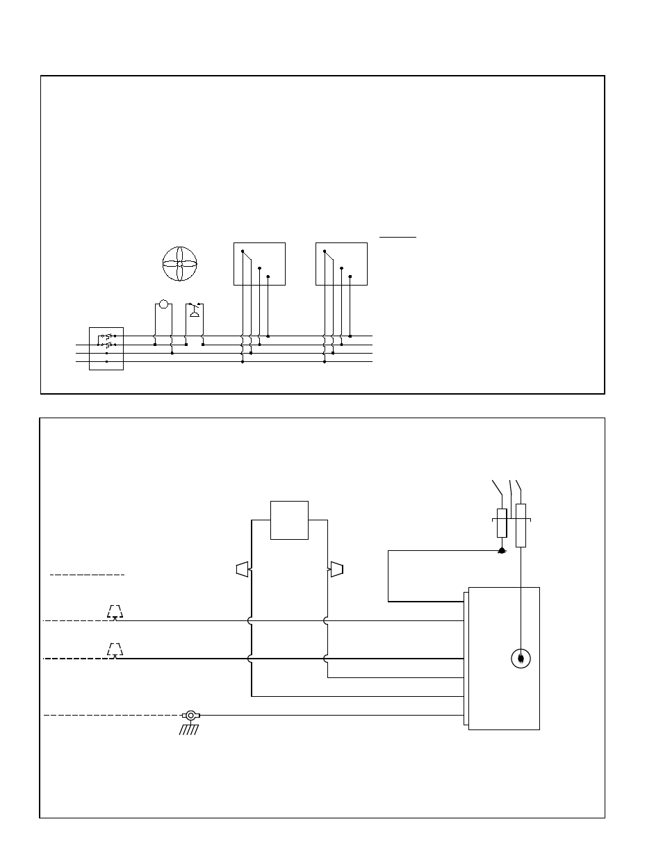
FIGURE 6C - With 24 VAC DIRECT SPARK IGNITION (DSI) 2-STAGE CONTROLS (Option
AG2R on RIHV100, RIHVN150, and RIHVN200 only)
• Electrical supply: 24 VAC - 60 Hz or 50 Hz - 1 Phase.
• Maximum total heater current draw: 0.96 Amps.
• Total heater power consumed: 23.1 VA (23.1W).
• 3-wire field service required to 2-stage thermostat. 4-wire thermostat cable required from thermostat to heater.
• Field wiring use 18/4 [18 AWG (0.8mm2)/4-conductor] solid class 2 thermostat cable having a minimum
insulation temperature of 140°F (60°C) between thermostat and heater. Maximum length is 125 feet (38m).
7.2 Electrical Requirements by Voltage and Control Types
(cont'd)
7.0 Electrical
(cont'd)
GND
(-)
(+24)
GGS
BL
R
2-Stage
Thermostat
C
G
R
W2
W1
R
BL
GGS
VR*
SW*
MV*
24 VAC DSI 2-STAGE HEATER ELECTRICAL SUPPLY AND THERMOSTAT WIRING*
LEGEND
(+24) = 24VAC Supply Voltage
(-) = Supply Neutral
GND = Earth Ground
MV* = Mechanical Ventilation*
VR* = Ventilation Relay*
SW* = Ventilation Interlock Switch*
(normally opened)
GGS = Green Ground Screw (inside control box)
BL = Blue Wire
- 24 VAC call for LOW heat
R (on heater) = Red Wire - 24 VAC call for HIGH heat
Use 18/4 solid class 2 thermostat cable between heater and thermostat with a maximum length of 125 feet (38m).
Heater 1
Heater 2
FIGURE 7A - 120 VAC Direct Spark
Ignition Electrical Connection Diagram
Greem Ground
Screw (GGS)
W(1)
BK(1)
W(2)
R(1)
W(3)
BK(2) - 1 & 2-burner
R(2) - 3 & 4-burner
O
O
Y
G
(-)
(+120)
GND
G
R(1)
W(2)
BK(1)
W(1)
Y
Combination
Gas Valve (CGV)
Ignition
Control
(IDC)
Flame
Sensor
(FS)
Spark
Electrode
(SE)
field wiring
Wire Colors
BK = Black
G = Green
O = Orange
R = Red
W = White
Y =Yellow
120 VAC – 60 Hz – 1 Phase
Heater Maximum Current Draw = 0.14 Amps.
Total Heater Power Consumed = 16.8 VA
NOTES:
•
Control is polarity sensitive.
•
Installer to provide and install #10 ring terminal required for ground service conductor to attach to green ground screw in
heater control box.
•
See Paragraphs 7.1 and 7.2 for detailed information on electrical supply and thermostatic control.
•
If any of the original wire as supplied with the appliance must be replaced, it must be replaced with wiring material having a
temperature rating of at least 302°F (150°C) and a minimum size of 16 AWG (1.0mm
2
).
7.3 Wiring Diagrams
P/N 131793R10, Page 12