0 maintenance and service -19, 1 maintenance procedures, 0 maintenance and service – Reznor RIHVL Unit Installation Manual User Manual
Page 17: 1 maintenance procedures and illustrations
11.0 Maintenance
and Service
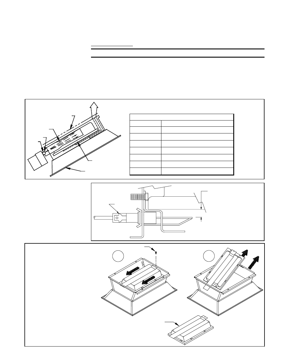
FIGURE 9 - Electrode
Assembly (Direct
Spark)
Electrode
Burner
Proper installation
results in 0.219 ± 0.032”
(5.6mm) clearance
from ceramic tile surface
to the sparking tips of
the electrode.
Refer to the illustrations below.
• FIGURE 8 illustrates general arrangement of heater operation.
• FIGURE 9 shows the direct spark assembly.
• FIGURE 10 illustrates burner removal.
Annual maintenance should be performed as follows:
CAUTION: Always wear protective goggles when cleaning heaters.
1. Disconnect all power sources related to the installation and close the gas supply
valve at the heater.
2. With an air hose of 20 PSI (140kPa) or less, blow off all accumulated dust and dirt.
Blow air over the ceramic tile (avoiding gasket material between tile) and
alternately into the venturi several times in succession. Be careful not to damage
gasket material between ceramic tiles. Damaging the material between the tiles
could lead to burner flashback.
E
D
C
B
A
G
F
LEGEND
Symbol
Item Description
A
Gas manifold
B
Gas orifice
C
Venturi
D
Optional heat deflector
E
Heater flue exhaust path
F
Ceramic tile surface
G
Standard reflector assembly
FIGURE 8 - General Arrangement
1
2
Screw
Ceramic Tile
Burner Assembly
(removed)
FIGURE 10 - Burner
Replacement
Burner Removal
Instructions
1) Remove screw and slide
burner backward.
2) Pull burner up and
outward.
Reverse the procedure to
re-install burner.
11.1 Maintenance
Procedures and
Illustrations
P/N 131793R10, Page 17