Index – Reznor RIHVL Unit Installation Manual User Manual
Page 19
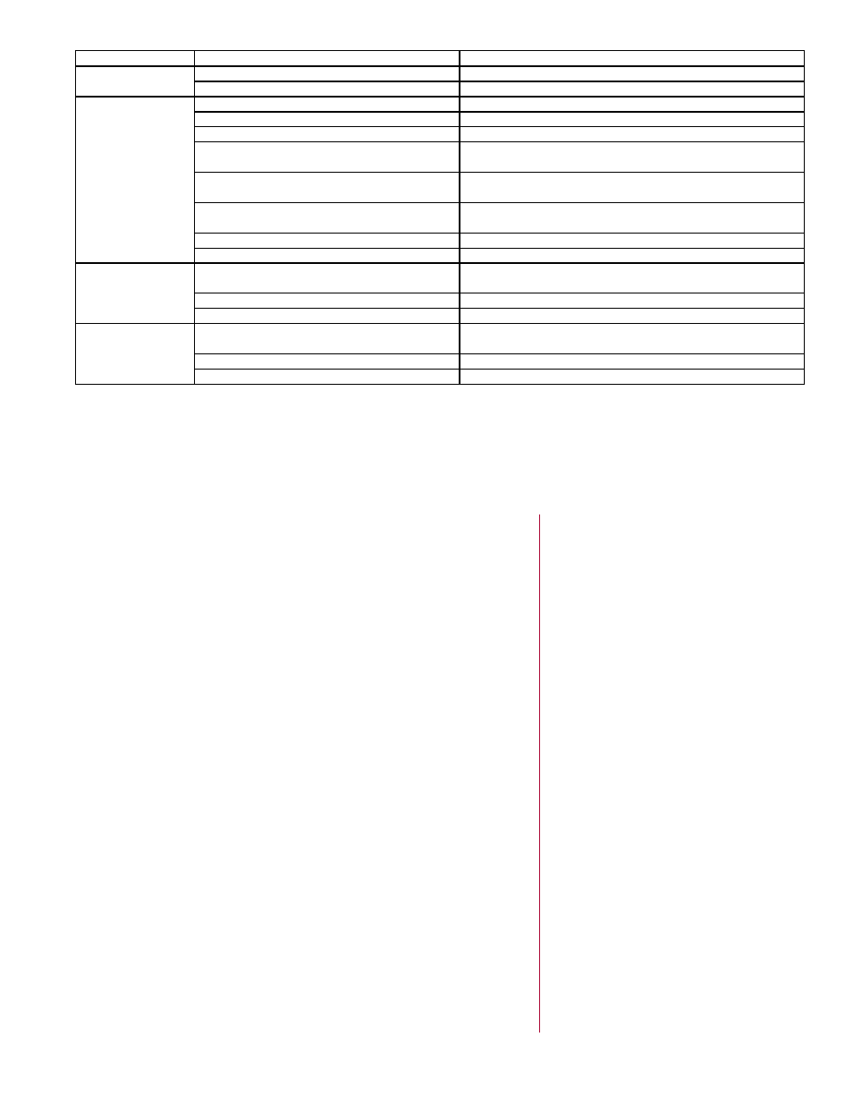
SYMPTOM
POSSIBLE CAUSE
CORRECTIVE ACTION
Dark spots on
ceramic surface
1. Foreign matter behind the ceramic surface 1. See Maintenance, Paragraph 11.1.
2. Foreign matter inside burner assembly
2. Replace burner assembly.
Low ceramic sur-
face temperature
1. Venturi obstructed (by spider web)
1. Clean with a bottle brush.
2. Foreign matter in venturi
2. See Maintenance, Paragraph 11.1.
3. Orifice partially blocked
3. See Maintenance, Paragraph 11.1.
4. Supply gas pressure low
4. Adjust supply regulator to 7” w.c. (18cm w.c.) for natural
gas, or 11” w.c. (28cm w.c.) for propane.
5. Manifold gas pressure low
5. Adjust heater regulator to 6” w.c. (15cm w.c.) for natural
gas, or 10” w.c. (25cm w.c.) for propane.
6. Manifold misaligned from excessive torque
applied on pipe at installation
6. Replace manifold.
7. Flue gases not adequately ventilated
7. See Ventilation Requirements, Paragraph 2.2.
8. Gas supply piping too small
8. Increase supply pressure or replace piping
2-Stage transition
from low-heat to
high-heat does not
happen
1. Ambient temperature is still in low-heat zone
of thermostat
1. Check thermostat manufacturers’ instructions.
2. Thermostat defective
2. Replace thermostat.
3. High-heat valve not opening
3. Replace high-heat valve.
2-Stage transition
from high-heat to
low-heat does not
happen
1. Ambient temperature has not reached low-
heat zone of thermostat
1. Allow time for ambient temperature to reach low-heat zone
of thermostat. Check thermostat manufacturer's instructions.
2. Thermostat defective
2. Replace thermostat.
3. High-heat valve not closing
3. Replace high-heat valve.
Index
A
Mounting Angle 7
B
C
Chain Hanging Arrangement 8
D
E
Electrical Connection Diagram 12
ELECTRICAL CONNECTION DIAGRAM 13
Electrode Assembly (Direct Spark) 17
G
General Arrangement 17
H
HAZARD INTENSITY LEVELS 2
High Altitude 3
I
L
M
P
R
S
SEQUENCE OF OPERATION 14
T
V
W
P/N 131793R10, Page 19