0 dimensions and clearances -7, 1 dimensions, 2 clearances – Reznor RIHVL Unit Installation Manual User Manual
Page 6: 0 dimensions and clearances, Warning
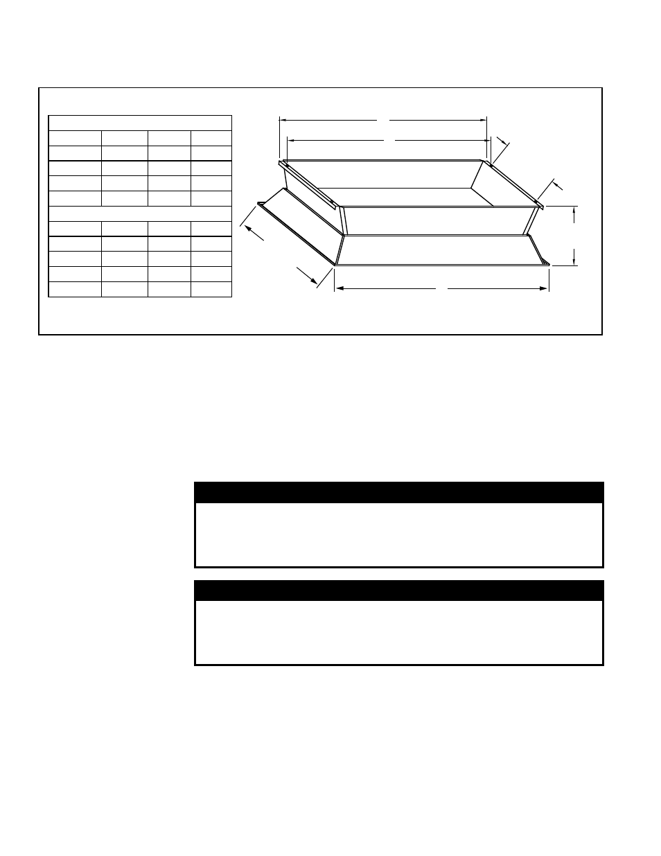
FIGURE 1 - Model RIH Dimensions - inches and (mm)
4.0 Dimensions and Clearances
4.2 Clearances
Dimensions - inches
Size
A
B
C
30, 50, 60
15-5/16
16-5/8
14-5/8
90, 100
23-15/16 25-1/4
23-1/4
120, 150
32-9/16
33-7/8
31-7/8
160, 200
41-3/16
42-1/2
40-1/2
Dimensions - mm
Size
A
B
C
30, 50, 60
389
422
371
90, 100
608
641
591
120, 150
827
860
810
160, 200
1046
1080
1029
This heater model must be mounted with minimum clearances between the combus-
tion surface and combustibles. The stated clearance to combustibles represents a
surface temperature of 90°F (50°C) above room temperature. Building materials with
a low heat tolerance (such as plastic, vinyl siding, canvas, tri-ply, etc.) may be subject
to degradation at lower temperatures. It is the installer's responsibility to assure that
adjacent materials are protected from degradation.
Locate the heater with respect to building construction and equipment so to provide
sufficient clearance and accessibility for servicing and cleaning.
WARNING
Single or multi-heater placement must be such that continuous
operation of the heater or heaters will not cause combustible
materials or materials in storage to attain a temperature in excess
of 150°F (66°C). See Hazard Levels, page 2.
WARNING
Under no circumstances should this heater be installed in
a combustible atmosphere or in a location where the heater
controls can be subjected to ambient temperatures in excess of
150°F (66°C). See Hazard Levels, page 2.
It is recommended that more distance than the minimum clearance be maintained
above the unit whether or not the construction is combustible. This will reduce and/or
eliminate hot spots and possible staining of painted ceiling surfaces. If the unit must
be close to the roof or ceiling, interpose a non-combustible baffle (twice the size of the
reflector) between the unit and the roof or ceiling. Allow at least 2" (52mm) between the
roof or ceiling and the non-combustible baffle. Allow at least 12" (305mm) between the
non-combustible baffle and the top of the heater.
To assure clearances to combustibles are maintained, signs
must be posted specify-
ing the maximum stacking height of material under and near the heater.
4.1 Dimensions
C
A
13"
(330mm)
B
23-23/32"
(603mm)
8-1/2"
(216mm)
NOTE: Four (4) mounting holes 3/8” (9.5mm) diameter for balanced
suspension are located by dimensions C x 13” (330mm).
P/N 131793R10, Page 6