Installation instructions for pressure null switch – Reznor RBL (Cabinet Blower) Unit Installation Manual User Manual
Page 7
Form I-RBL, P/N163219R2, Page 7
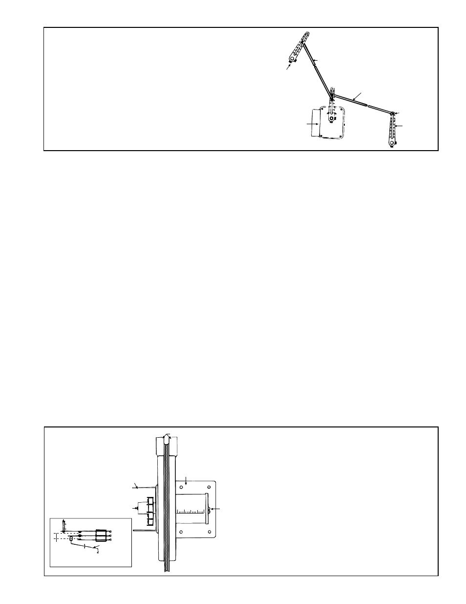
Outside Air
Damper
CLOSED
Return Air
Damper
OPEN
Rod for Outside
Air Damper
Set Screw
Outside Air
Damper Arm
Return Air
Damper Arm
Rod for Return
Air Damper
Damper
Motor
Damper Linkage Instructions -- When units are equipped
with dampers, the dampers are closed during shipment.
When there are both return air and outside air dampers, the
return damper linkage must be adjusted prior to use.
1. Loosen the set screw on the return air damper rod at the
damper arm.
2. Manually open the return air dampers. While the dampers
are opening, the damper rod and arm will automatically
move to their correct positions.
3. Tighten the set screw.
FIGURE 11 - Example of Outside Air and Return Air
Damper Linkage
Pressure Null Switch
(Used to control
Outside Air Dampers in
Inlet Air Option AR23)
The pressure null switch used in Option AR23 is a Dwyer #1640-0 with a range of .01-
.20" w.c. It is shipped separately for field installation. Refer to the following paragraphs
and the manufacturer's installation instructions included with the switch.
Description and Application (See FIGURE 12) - The pressure null switch is a dia-
phragm operated differential pressure switch used in makeup air applications to con-
trol building pressure. It maintains a selected positive or negative pressure setpoint by
changing the amount of outside air being introduced to the building through the modu-
lating outside air dampers. As more pressure is required in the building, the pressure
null switch activates the damper motor driving the outside air damper towards the full
open position and the recirculated air damper towards the closed position. Conversely,
as less pressure is required, the switch drives the dampers in the opposite direction.
Installation Instructions for Pressure Null Switch
1. Select an indoor location free from excessive vibration where oil or water will
not drip onto the switch and where ambient temperature will be within a range of
-30°F (dry air) to 110°F.
2. Mount the switch with the diaphragm in a vertical plane. The switch is position
sensitive and is calibrated to operate properly when the diaphragm is vertical.
Mount switch securely.
3. Connect the pressure taps on the top of the switch to sources of air pressure
differential. Metal tubing with 1/4" O.D. is recommended, but any tubing system
which will not unduly restrict the air flow may be used. To maintain a positive
building pressure, vent the low pressure tap to the outdoors and allow the
high pressure tap to monitor building pressure. To maintain a negative building
pressure, reverse the functions of the high and low pressure taps. In either case,
be sure that the outdoor vent is protected from the wind and screened from
insects.
4. Adjustment of the Switch - The "HIGH" actuation point of the null switch is
indicated on a calibrated scale secured to the transparent range screw enclosure.
Building pressure is set by turning the adjustment screw. The "Low" actuation
Electric Box
Span
Adjust
Screw
Mounting Plate
Pressure Taps
Low
High
Pressure
Adjust
Screw
Span of
floating
contact
Increasing
Decreasing
Linkage to
Diaphragm
Low
Common
High
Span Adjustment
Switching action in the pressure null
switch
IMPORTANT: To eliminate shipping damage to
the switch contacts, the manufacturer reduced
the span adjustment to zero before shipping. The
span should be adjusted prior to using the switch.
(If the switch has been installed, disconnect the
vent tube so that the null switch is in a neutral
position.) Remove the electrical box cover and
while observing the contacts, turn the span
adjustment screw slowly in a clockwise direction.
Continue turning the adjustment screw until you
are able to see gaps between the common and
both the low and high contacts. A minimum gap
provides the greatest sensitivity. The wider the
gap the lower the sensitivity.
FIGURE 12 - Pressure
Null Switch (used with
Inlet Air Option AR23)