Reznor RBL (Cabinet Blower) Unit Installation Manual User Manual
Page 3
Form I-RBL, P/N163219R2, Page 3
A
B
4x4 Treated Lumber
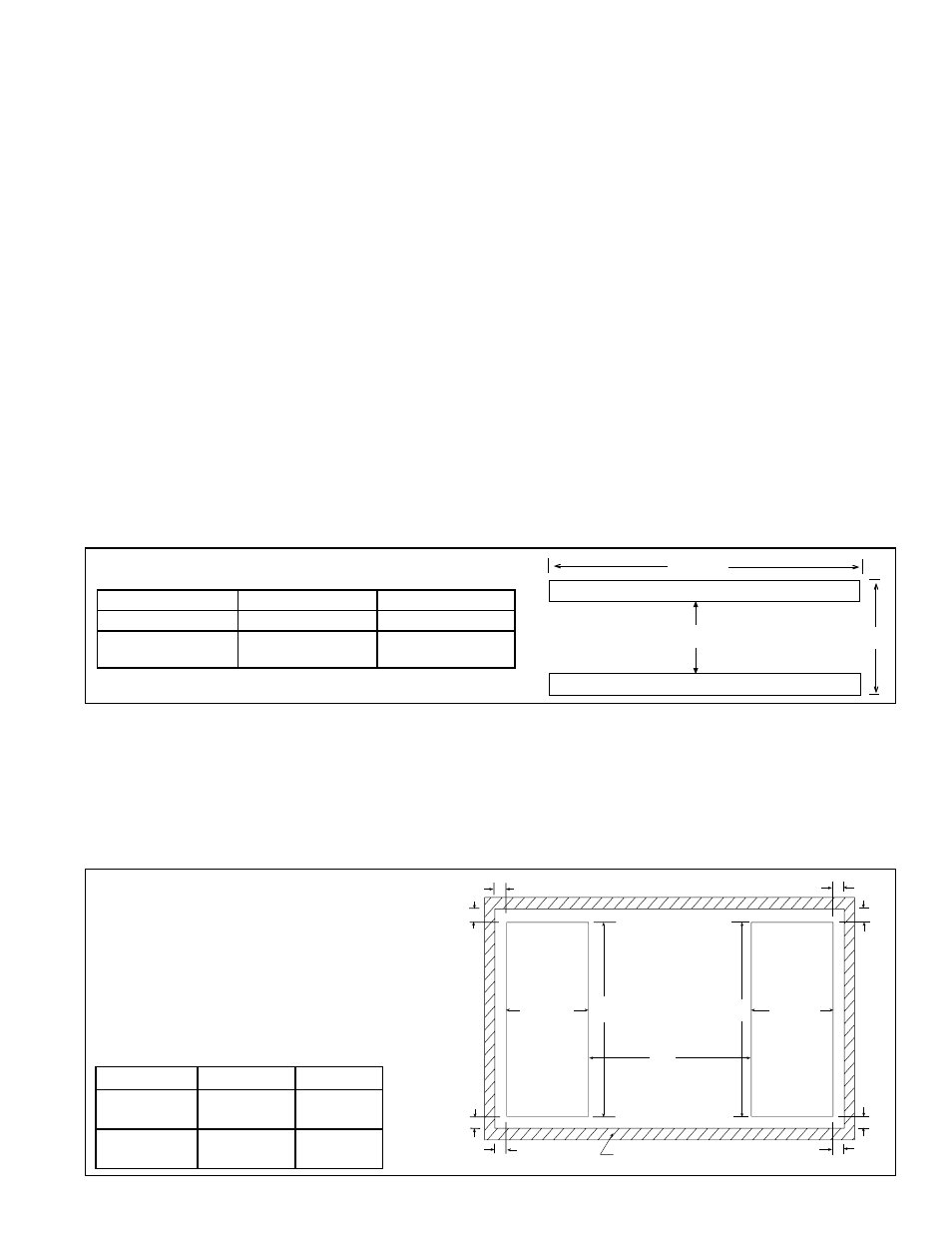
FIGURE 3 - Support Rail Dimensions
Configuration
A
B
Standard Model RBL 59-1/16" (1500mm) 53-9/16" (1361mm)
Model RBL with
Downturn Cabinet
82-1/16" (2084mm) 53-9/16" (1361mm)
Mounting on a Roof Curb - Whether using an optional roof curb available for the cabinet or a field-supplied curb, the
curb must be square and level and a minimum height of 14" (356mm). The top surface of the roof curb must be caulked
with 1/4" x 1-1/4" sealant tape or 1/4" beads of suitable sealant. The cabinet must be sealed to the curb to prevent water
leakage into the curb area due to windblown rain and capillary action. Except for the curb assembly details, the informa-
tion and requirements in this section apply to both an optional curb and a field-supplied curb. See
FIGURE 5 and curb
installation instructions.
Bottom Duct Connections - Both the optional return air opening and the opening in the downturn plenum have duct
flanges. Duct opening sizes and spacing in relation to an optional roof curb are shown in
FIGURE 4.
The blower cabinet may be mounted on an optional roof curb, a field-supplied roof
curb, or field supplied supports. If the system has a downturn plenum and/or a bottom
return air opening, a roof curb is recommended to provide a weatherproof installation
as well as more workable clearances for ductwork. The blower cabinet curb cap is not
designed to be placed directly on the roof surface. When positioning rooftop equip-
ment, it is recommended that the air inlet does not face into the prevailing wind.
Mounting on Field Supplied Supports (without a roof curb) - Prior to installation,
be sure that the method of support is in agreement with all local building codes and is
suited to the climate. If considering this type of installation in snow areas, it is recom-
mended that the 4x4 wooden rails underneath the unit be on cross-support structure
at least 12" (305mm) higher than the roof surface. Whether the supports are being
mounted directly on the roof or being placed "up" on additional structure, the horizontal
length of the unit should be supported by two 4x4 treated wooden rails. Cut the rails
to the appropriate length (Dimension "A") in
FIGURE 3. (NOTE: Although dimensions
are included for units with a downturn plenum cabinet, it is strongly recommended that
a roof curb be used on an installation with a downturn plenum cabinet and/or a bottom
return air duct.) Space the 4x4 wooden support rails (See "B" Dimension in
FIGURE 3)
so that the curb cap "skirt" will fit over the edge of the boards with the rail setting inside
the horizontal length of the curb cap.
If the rails are being laid directly on the roof, position them as shown in
FIGURE 3. Set
the unit on the rails.
NOTE: It is recommended that there be a minimum of 14" between
the bottom of the inlet air hood (see Paragraph 5.1.2) and the mounting surface.
If the treated wooden rails are not placed directly on the roof surface, cross supports
should be placed underneath the rails at the ends of the cabinet. The field-supplied,
weather-resistant cross-support structure must be adequate for the weight of the unit
and run the entire width of the cabinet supporting the 4x4 wooden rails.
1-5/8
(41)
1-5/8
(41)
1-5/8 (41)
1-5/8 (41)
1-5/8 (41)
1-5/8 (41)
19-1/2
(495)
19-1/2
(495)
H
H
G
Bottom
Return
Duct
Supply
Duct
(applies to
RBL with
downturn
only)
Roof Curb
1-5/8
(41)
1-5/8
(41)
Dimensions
G
H
Standard RBL
Cabinet
NA
47-5/8"
(1210mm)
RBL w/Down-
turn Plenum
55-13/16"
(1418mm)
47-5/8"
(1210mm)
FIGURE 4 - Roof Curb and Optional Duct
Opening Dimensions - inches (mm)
Return and Supply Duct Dimensions and
Locations are in relation to Reznor Optional
Roof Curbs.)
1-5/8" (41mm) is measurement from duct
opening to
inside edge of roof curb.
NOTE: Cut duct openings 1" (25mm) larger
than the duct size for installation clearance.