2 outside air hoods, Figure 6 - filter arrangements – Reznor RBL (Cabinet Blower) Unit Installation Manual User Manual
Page 5
Form I-RBL, P/N163219R2, Page 5
RBL
CFM
2" Disposable Filters
(Option AW7)
2" Permanent Filters
(Option AW9)
2" Pleated Filters
(Option AW11)
5000
0.04
0.08
0.10
6000
0.06
0.12
0.14
7000
0.08
0.16
0.19
8000
0.10
0.21
0.25
9000
0.13
0.26
0.31
10000
N/A
0.33
0.39
11000
N/A
0.40
0.47
12000
N/A
0.48
0.56
13000
N/A
0.56
N/A
14000
N/A
0.65
N/A
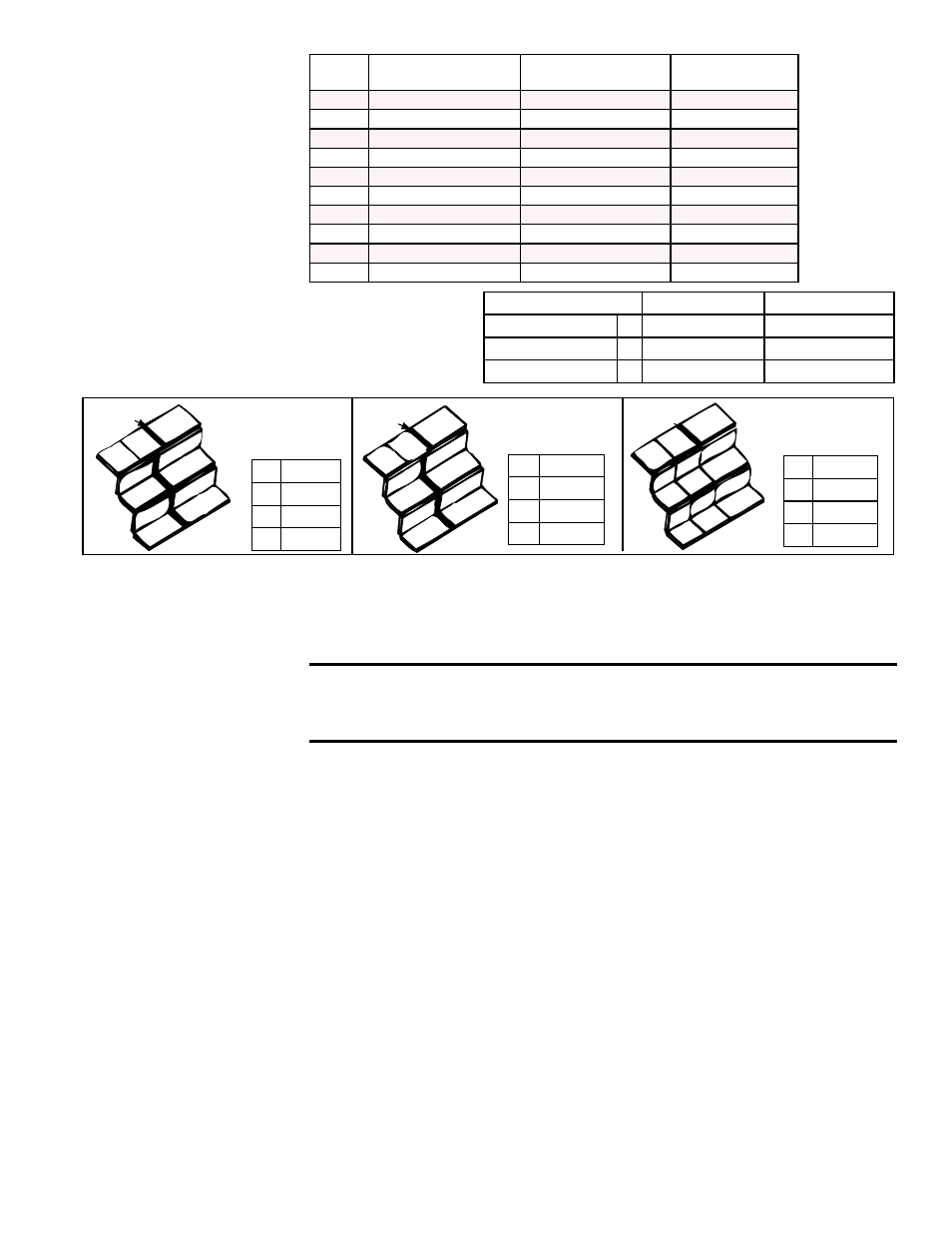
B
A
A
D
D
D
D
C
C
C
C
Blockoff
Plates
A
B
C
D
A
D
D
D
C
C
C
Blockoff
Plates
D
D
D
D
B
A
A
C
C
C
C
C
C
C
C
Blockoff
Plate
Disposable Filter Range --
0 to 400 FPM
Pleated Filter Range --
0 to 500 FPM
Permanent Aluminum Filter
Range -- 0 to 600 FPM
Disposable
Filters (Option
AW7)
Pleated Filters
(Option AW11)
Permanent Filters
(Option AW9)
NOTE: If the unit was manufactured prior to 9/91;
filter sizes and arrangements are different; refer to
Parts Replacement Form P-RG/RP/RBL or contact
your distributor.
Type of Filters
Average Efficiency Average Arrestance
Disposable
2"
Less than 20%
80%
Permanent
2"
Less than 20%
64% to 67%
Pleated Disposable 2"
30% to 35%
90% to 93%
A 16 x 16
B 16 x 25
C 12 x 25
D 12 x 30
A 16 x 16
B
16 x 25
C 12 x 16
D 12 x 26
A 16 x 16
B
16 x 25
C
12 x 25
D
12 x 32
FIGURE 6 - Filter Arrangements
5.1.2 Outside Air
Hoods
100% Outside Air Hood, Option AS2 - Outside air hood (Option AS2) is a weather-
ized, screened hood designed to be field assembled and installed around the horizon-
tal inlet air opening of the blower cabinet. The air hood includes a louver assembly
designed to help eliminate moisture from the inlet air. Complete installation instructions
are packaged with the air hood option.
CAUTION: It is recommended that the inlet to the outside air
hood NOT be facing into the prevailing wind. Allow 14" minimum
clearance from the bottom of the air hood to the mounting surface.
NOTE: Either a
manufacturer designed
optional air inlet hood as
shown in Paragraph 5.1.2
or an evaporative cooling
module as shown in
Paragraph 5.1.4 is required
to ensure complete weather
resistance.
Filter Pressure
Drops (" w.c.)
Installation Instructions - 100% Outside Air Hood (See FIGURE 7B)
To avoid possible damage, it is recommended that the outside air hood be installed
after the cabinet has been placed on the roof. The air hood should be installed before
the blower is operated. Do not install the hood while the blower is in operation. All
screw ends except those across the bottom are inside the air hood.
1. Top Panel -- On the air inlet side of the blower cabinet, remove the factory-
installed screws attaching the blower cabinet top. Slide the air hood top panel
underneath the edge of the blower cabinet top.
The edge of the air hood top
panel must be between the blower cabinet top and the end panel. Reinsert all
of the sheetmetal screws.
2. Side Panels -- Slide the air hood right side panel into the groove in the blower
cabinet end panel. Be sure that the side panel is underneath and to the inside of
the air hood top panel. Attach to the blower cabinet and the air hood top using the
required number of sheetmetal screws. Repeat with the left side panel.
3. Bottom Panel -- Position the air hood bottom panel so that it is to the inside of the
two side panels and
above the factory-installed support angle. Attach to the side
panels.
If the bottom panel does not rest tightly against the support angle, follow these
instructions to adjust the position of the support angle:
a) Slightly loosen (do not remove the screws).
b) Slide the support angle up so that it is against the bottom panel.
c) Tighten the screws.