0 commissioning and start-up – Reznor RBL (Cabinet Blower) Unit Installation Manual User Manual
Page 11
Form I-RBL, P/N163219R2, Page 11
Voltage
/Phase
Motor
HP
Wire
Gauge
BX
Cable
208/1 or
230/1
1 - 2
14
3/8"
3
10
1/2"
5
8
1/2"
7.5
6
1"
10
4
1"
208/3 or
230/3
1 - 4
14
3/8"
5
12
3/8"
7.5
10
1/2"
10
8
1/2"
15
6
1"
20
4
1"
460/3
1 - 7-1/2
14
3/8"
10
12
3/8"
15
10
1/2"
20
8
1/2"
575/3
1 - 7-1/2
14
3/8"
10 - 20
10
1/2"
Field-supplied Wiring
Size from Disconnect
to Electrical Box for
Connection to Motor
Contactor or Starter
Disconnect Switch
-
A disconnect switch is a
required part of this installation. Switches are
available, as options or parts, or may be pur-
chased locally. When ordered as an optional
component, the disconnect switch is shipped
separately.
The disconnect switch may be fusible or non-fus-
ible. When installing, be careful that the conduit
and switch housing are clear of cabinet panels.
Allow at least four feet (1.2M) of service room
between the switch and removable panels.
Convenience Outlet Option - When a conve-
nience outlet (Option BC) is included, a separate
power supply must be provided to the receptacle.
This circuit MUST BE on a ground fault breaker to
meet requirements. All wiring to the convenience
outlet must meet National Electrical Code ANSI/
NFPA No. 70 (latest edition) and any local or util-
ity codes that apply.
Control Wiring
Field Control Wiring - Length and Gauge
Total Wire Length
Distance from Unit to Control
Minimum Recommended Wire Gauge
150 ft (46M)
75 ft (23M)
#18 gauge
250 ft (76M)
125 ft (38M)
#16 gauge
350 ft (107M)
175 ft (53M)
#14 gauge
1
2
3
5 4
6
7
8
9
10
11
12
13
1415 16
18 19
17
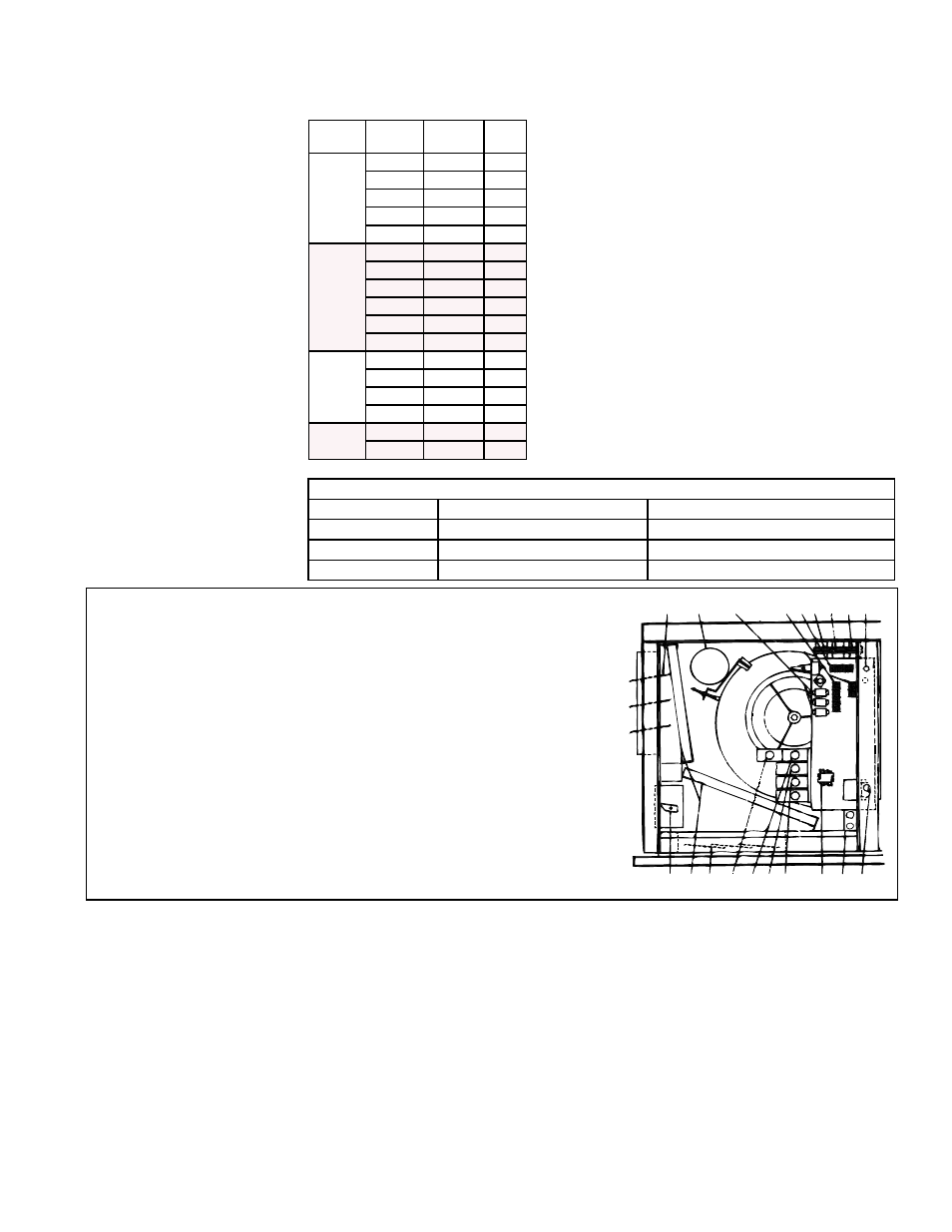
FIGURE 16 - Location of Electrical Connections and
Standard and Optional Controls
(Illustration is not an RBL cabinet but controls are in same location
in a Model RBL.)
1) Line Voltage Connection (field)
2) Optional Convenience Outlet
3) Blower Motor Contactor or Starter
4) Optional Outside Air or Return Air
Controller
5) Optional Mixed Air Controller
6) Optional Potentiometer
7) Optional Potentiometer
8) Optional Return Air Dampers
9) Optional Filters
10) Optional Two-Position or
Modulating Damper Motor
11) Optional Outside Air Dampers
12) Blower Motor (Drive on opposite
Side) - Available in Open, TEFC,
Energy Efficient or Two-Speed
13) Optional Control Relays (as
required - 8 maximum)
14) Low Voltage Terminal Strip
15) Line Voltage Terminal Strip
16) Control Transformer
17) Control Transformer (as
required)
18) Optional Damper Motor
Transformer
19) Low Voltage Connection (field)
7.0 Commissioning
and Start-Up
Be certain electrical supply matches voltage rating on unit (see rating plate).
Check all field wiring against wiring diagram. Be sure wire gauges are as required
for the electrical load. This information appears on the wiring diagram.
Be certain that electrical entries are sealed against the weather.
See that fuses or circuit breakers are in place and sized correctly.
Check blower pulley and motor pulley to be sure they are secure to shafts. Check
belt tension; see Paragraph 5.3.
If the unit is equipped with outside air and return air dampers, adjust the damper
linkage. See Paragraph 5.1.3.
Close all panels tightly.
Return this book to the "Owner's Envelope" for future reference.
Check the wiring diagram and literature supplied with the cabinet for operation of fac-
tory-installed optional controls. See
FIGURE 16 for location of electrical connections
and available standard and optional controls.