0 mechanical (cont'd), 1 unit inlet air (cont'd), 3 optional dampers and damper controls – Reznor RBL (Cabinet Blower) Unit Installation Manual User Manual
Page 6: 2 outside air hoods (cont'd)
Form I-RBL, P/N163219R2, Page 6
Top Panel (edge must be
underneath cabinet top)
Left Side
Panel
Right Side
Panel
Factory-assembled
Louver Assembly
including Moisture
Eliminating Louvers
and Screen
Bottom
Panel
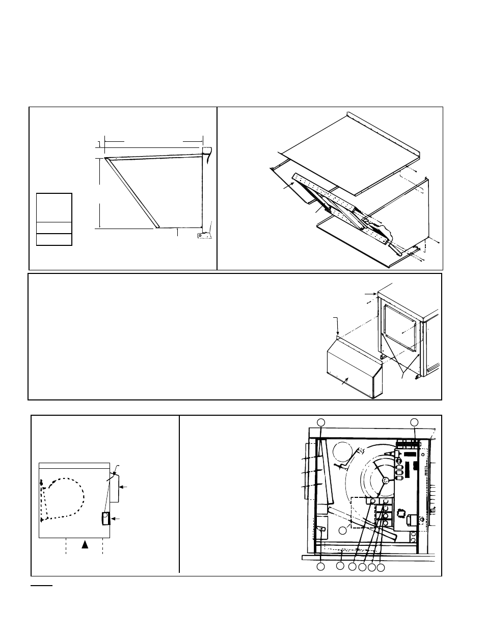
FIGURE 7B - Assembly
Drawing of Option AS2
Outside Air hood
FIGURE 7A - Dimensions of Optional
Outside Air Hood
(NOTE: The width of the outside air hood is the same
as the width of the blower cabinet.)
Optional 100%
Outside Air Hood
43-17/32 (1106mm)
4-5/8
(117mm)
31-11/32
(796mm)
14 (356mm)
minimum
Screened Inlet Air Hood for 30% Outside Air Opening, Part of Inlet
Air Options AR6 and AR7) -The assembled outside air hood included
in the air inlet options that have a 30% outside air opening (Option AR6
or AR7) is shipped separately for field installation.
Installation Instructions - 30% Outside Air Hood
1. On the inlet air side of the blower cabinet, remove the factory
installed screws attaching the blower cabinet top.
2. Slide the air hood top flange underneath the lip of the blower cabi-
net top and the sides into the vertical slots. The air hood flange
must be between the blower cabinet top and the cabinet end panel.
3. Reinsert all of the sheetmetal screws.
Blower
Cabinet
Remove two corner
and complete row
of screws
Slide top
flange
underneath
the cabinet
top
Vertical Slots -
Slide side flanges
into slots
30% Outside
Air Hood
Width of
Outside
Air Hood
58-7/8"
1495mm
5.0 Mechanical
(cont'd)
5.1 Unit Inlet Air
(cont'd)
1) Damper Motor
2) Return Air Damper
3) Potentiometer
4) Potentiometer
5) Mixed Air Controller
6) Warm-up Control
7) Outside Air Damper
8) Damper Motor Transformer
7
8
1
2
3 4 5 6
9
FIGURE 9 - Location of Controls
for 30% Outside Air Hood
(FIGURE 8) and Damper Option
AR6 or AR7
FIGURE 10 - Control
Locations for 100%
Outside Air and 100%
Return Air Damper
Options
Blower
30% Outside
Air Damper
30% Outside
Air Hood
Damper Motor
Optional
Bottom
Return Air
5.1.3 Optional Dampers and Damper Controls
NOTE: The illustrations in FIGURES 9 & 10 are intended to show location only of various air control accessories and
do not represent suggested combinations of accessories.
Attach the support angle to the air hood bottom panel. The bottom panel of the
air hood and the support angle should be tight together; do not draw with the
sheetmetal screws.
4. Louver Assembly -- With the intake screen toward the inside of the hood, posi-
tion the pre-assembled vertical louver assembly in the inlet opening of the air
hood. Using the remaining sheetmetal screws, attach the louver assembly to the
air hood side panels using the holes provided.
5.1.2 Outside Air Hoods (cont'd)
FIGURE 8 - Installation of Air Hood with 30% Outside Air Opening Option