0 mechanical, 0 electrical supply and connections, 3 blowers, belts, and drives (cont'd) – Reznor RBL (Cabinet Blower) Unit Installation Manual User Manual
Page 10: Cont'd), Figure 15 - split taper bushing
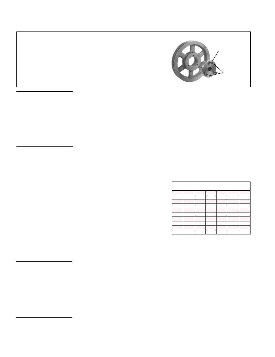
Form I-RBL, P/N163219R2, Page 10
5.0 Mechanical
(cont'd)
Blower Pulley - Some blower pulleys require the use of a split taper
bushing in the blower pulley. These split taper bushings must be loos-
ened in order to remove the pulley. Follow these instructions to loosen
the bushing:
a) Notice that there are three cap screws in the bushing and two holes
without screws, called push-off holes.
b) Remove the three cap screws.
c) Put two of the cap screws into the two push-off holes. Tighten these
two screws evenly until the pulley is loosened.
d) Pulley may now be removed from the shaft.
Blower Bearings - The blower bearings on systems with less than a 10 HP motor
(standard blower) are permanently lubricated cartridge ball bearings and do not require
greasing.
The blower bearings on systems equipped with 10-20 HP motor are pillow block ball
bearings and are equipped with a grease fitting. (
NOTE: Units manufactured prior
to 1/91 with a 10 HP motor may have permanently lubricated ball bearings.) These
bearings should be lubricated twice a year with a high temperature, moisture-resistant
grease. (Type NLGI-1 or -2 standard grease is recommended.) Be sure to clean the
grease fitting before adding grease. Add grease with a handgun until a slight bead of
grease forms at the seal. Be careful not to unseat the seal by overlubricating. NOTE:
If unusual environmental conditions exist (temperatures below 32°F or above 200°F;
moisture; or contaminants), more frequent lubrication is required.
Blower Rotation - Each blower housing is marked for proper rotation. Rotation may be
changed on single-phase motors by re-wiring in the motor terminal box. Three-phase
motors may be reversed by interchanging two wires on the 3-phase supply connec-
tions.
FIGURE 15 - Split Taper Bushing
(3) Cap
Screws
(2) Push-
Off Holes
All electrical wiring and connections, including electrical grounding MUST be made in
accordance with the National Electric Code ANSI/NFPA No. 70 (latest edition) or, in
Canada, the Canadian Electrical Code, Part I-C.S.A. Standard C22.1. In addition, the
installer should be aware of any local ordinances or gas company requirements that
might apply.
Check the plate on the cabinet for the supply voltage and current requirements. A
separate line voltage supply with fused disconnect switch should be run directly from
the main electrical panel, making connection to leads in the junction box. All external
wiring must be within approved conduit and have a minimum temperature rise of 60°C.
Conduit from the disconnect switch must be run so as not to interfere with the service
panels of the cabinet. The unit must be electrically grounded in accordance with the
national Electrical Code, ANSI/NFPA No. 70 (latest edition or CSA Standard C22.1
when installed, if an external electrical source is used.
6.0 Electrical
Supply and
Connections
5.3 Blowers, Belts, and Drives (cont'd)
CAUTION: If any of
the original wire as
supplied with the
appliance must be
replaced, it must be
replaced with wiring
material having a tem-
perature rating of at
least 105°C.
If the installation includes field-installed options that require electrical connections, con-
sult the instruction sheet and wiring diagram supplied in the option package. Optional
shipped-separate controls could include system switches, potentiometer, a pressure
null switch, or a combination of these controls. Install these according to the manufac-
turer's instructions packed with the cabinet.
Motors - Use an amp meter to check
motor amps. The chart below lists full load
amps for various HP and voltages. Amps
may be adjusted downward by reducing
blower RPM or by increasing duct system
static pressure.
This chart should not be interpreted as the
exact amps. See the motor rating plate for
specific amps.
Full Load Amps - Blower Motors (Open)
(Single Speed- Average Values)
HP
208/1 230/1 208/3 230/3 460/3 575/3
1
7.5
6.5
3.7
3.2
1.6
1.1
1-1/2
8.3
7.5
5.6
5.0
2.7
1.6
2
10.0
10.2
7.0
6.6
3.5
2.1
3
14.0
12.4
9.0
8.6
4.3
3.6
5
28.0
26.0
13.4
13.2
6.6
5.4
7-1/2
35.0
32.0
22.5
19.4
9.7
7.8
10
42.0
38.0
30.0
26.0
13.0
10.4
15
43.1
39.0
19.5
16.0
20
58.7
53.0
26.5
21.2
CAUTION: If the
blower is unused
for more than three
months, bearings
with a grease fitting
should be purged
with new grease
prior to start-up.