Ga s va lv e – Reznor VCT Unit Installation Manual User Manual
Page 9
9
If any of the original wire as supplied with the appliance must be replaced, it must be replaced
with wiring material having a temperature rating of at least 220°F/105°C
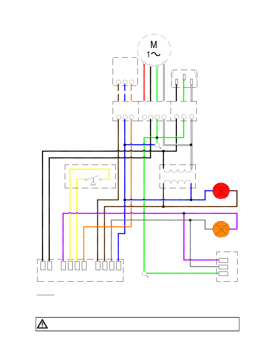
Figure 6. Internal Burner Wiring Diagram. (VCS)
L
N
E
L1
Gas Control
MV
X
C
CO
M
W1
PS0
PS1
IN
D
R
E
G
a
s
Va
lv
e
C
M
E
NOTES:-
Power On light is permanently illuminated when 120V / 60 Hz AC external supply is connected to burner.
Additional wiring is required to install a thermostat and / or time clock.
Wire specification:- 18 AWG (1.0mm²), Tri-rated, 105°C
Pressure Switch
120v/24VAC 60Hz
Transformer
Power ON (red)
BK
BK
Y
O
BR
GR
BL
KEY:
BL - BLUE
BK - BLACK
BR - BROWN
GR - GREY
G - GREEN
W - WHITE
Y - YELLOW
O - ORANGE
P - PURPLE
BR
Y
P
Y
Y
W
G
BK
W
G
BL
BR
P
GR
P
GR
BR
W
BK
L
N
E
120V AC
Supply
BK
N
E
120V AC Fan
Terminals
C
W1
R
24V Stat
Terminals
O
BL
BR
Burner On (amber)
C
W1
R
Optional
24V single
stage
Thermostat
R
W
G
BK
W
G
BK
O
BL
BR
G
F
E