Gas v alve – Reznor VCT Unit Installation Manual User Manual
Page 10
10
If any of the original wire as supplied with the appliance must be replaced, it must be replaced
with wiring material having a temperature rating of at least 220°F/105°C
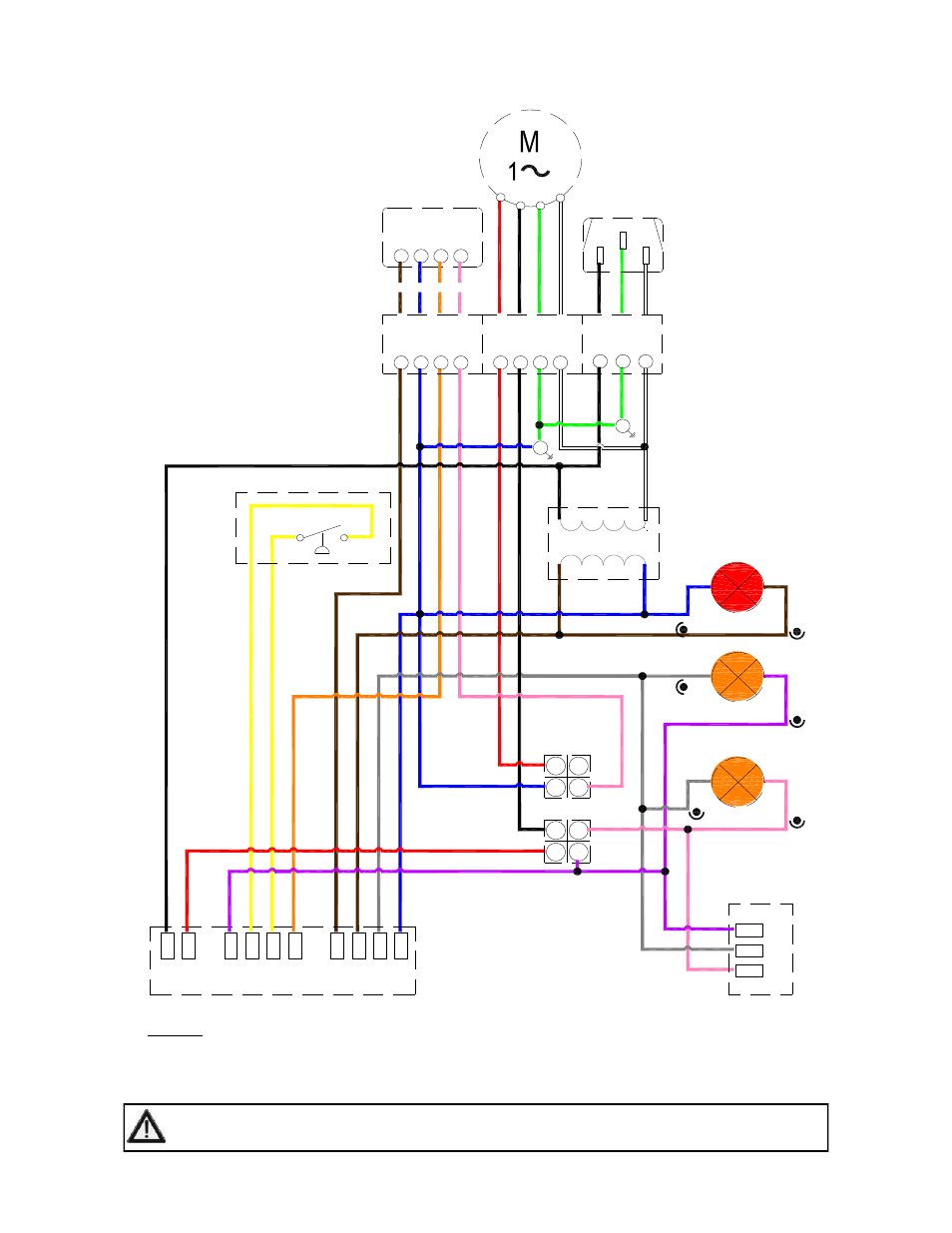
Figure 7b. Internal Burner Wiring Diagram. (VCT)
L
N
E
L1
Gas Control
MV
X
C
COM
W1
P
S0
P
S1
IN
D
R
E
G
as
V
alve
C
M
HI
NOTES:-
Power On light is permanently illuminated when 120V / 60 Hz AC external supply is connected to burner.
Additional wiring is required to install a thermostat and / or time clock.
Wire specification:- 18 AWG (1.0mm²), Tri-rated, 105°C
Pressure Switch
120V/24VAC 60Hz
Transformer
Power ON (red)
BK
R
Y
O
BR
GR
BL
KEY:
BL - BLUE
BK - BLACK
BR - BROWN
GR - GREY
G - GREEN
K - PINK
R - RED
W - WHITE
Y - YELLOW
O - ORANGE
P - PURPLE
BR
Y
P
Y
Y
R
W
G
BK
W
G
BL
BR
P
GR
P
GR
K
BR
W
BK
L
N
E
120V AC
Supply
BK
F1
N
E
F2
120V AC Fan
Terminals
High Fire
K
GR
24V AC
RELAY
21
14
24
11
A2
12
22
A1
High Fire
Relay
COIL
NC
NO
COM
C
W2
W1
R
24V AC Stat
Terminals
K
O
BL
BR
Low Fire
(amber)
C
W2
W1
R
24V Two stage
Thermostat
R
W
G
BK
W
G
BK
BL
R
BK
R
K
O
BL
BR
E