110v thermostat other burners burner 1, 120v thermostat – Reznor VCT Unit Installation Manual User Manual
Page 8
8
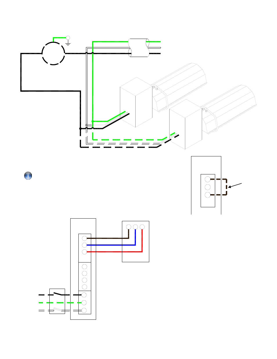
Figure 5b. Single and Multiple Heater Installations 120V Control (VCS)
Supply circuit
120V 60Hz 1 Ph
L2
L1 (HOT)
GND
T
110V Thermostat
other burners
Burner 1
120V Thermostat
KEY:
G-GREEN
W-WHITE
BK-BLACK
BK
G
W
W
G
BK
BK
Other burners
T
Figure 5c. External Wiring Schematic (VCS)
If heaters are wired using the method shown above, a link wire must be
fitted to the burner terminals as shown in the diagram opposite.
Link
F2
F1
R
C
W1
24V AC
Terminals
(120V AC Fan
Terminals)
120V AC
Supply
24V AC Single Stage
Thermostat (Ext.)
R
C
W1
Burner 1
E
N
L
N
E
BK
R
BL
BK
G
W
KEY:
BK-BLACK
BL-BLUE
R-RED
G-GREEN
W-WHITE
Notes:
Use 18/4 class 2 thermostat cable
between heater and thermostat.
Max. length @ 18 Awg (0.8mm²) =
100ft.
Only one burner can operate from one
thermostat as supplied.
When servicing heaters ensure the
electricity supply is isolated from the
mains supply.
120V AC supply is still present at each
burner when the thermostat is
switched off.
R
C
W1
24V AC
Terminals
Burner