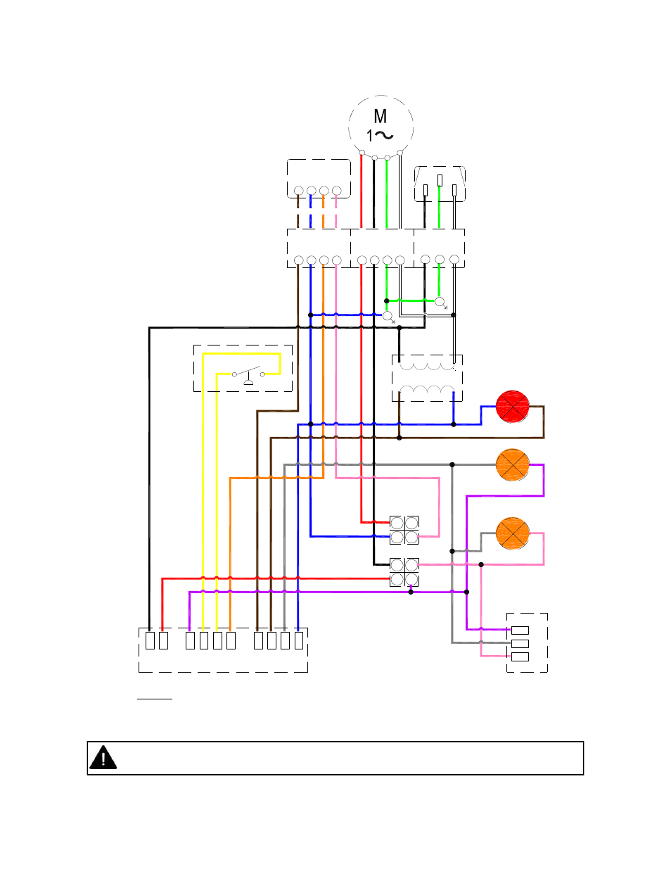
Figure 6. internal burner wiring diagram – Reznor VPT Unit Installation Manual User Manual
Page 8
8
If any of the original wire as supplied with the appliance must be replaced, it must be replaced
with wiring material having a temperature rating of at least 220°F/105°C
L
N
E
L1
Gas Control
MV
X
C
COM
W1
P
S0
P
S1
IN
D
R
E
G
as
V
alve
C
M
HI
NOTES:-
Power On light is permanently illuminated when 120V / 60 Hz AC external supply is connected to burner.
Additional wiring is required to install a thermostat and / or time clock.
Wire specification:- 18 AWG (1.0mm²), Tri-rated, 105°C
Pressure Switch
120V/24VAC 60Hz
Transformer
Power ON (red)
BK
R
Y
O
BR
GR
BL
KEY:
BL - BLUE
BK - BLACK
BR - BROWN
GR - GREY
G - GREEN
K - PINK
R - RED
W - WHITE
Y - YELLOW
O - ORANGE
P - PURPLE
BR
Y
P
Y
Y
R
W
G
BK
W
G
BL
BR
P
GR
P
GR
K
BR
W
BK
L
N
E
120V AC
Supply
BK
F1
N
E
F2
120V AC Fan
Terminals
High Fire
K
GR
24V AC
RELAY
21
14
24
11
A2
12
22
A1
High Fire
Relay
COIL
NC
NO
COM
C
W2
W1
R
24V AC Stat
Terminals
K
O
BL
BR
Low Fire
(amber)
C
W2
W1
R
24V Two stage
Thermostat
R
W
G
BK
W
G
BK
BL
R
BK
R
K
O
BL
BR
E
Figure 6. Internal Burner Wiring Diagram.
- UDAP Unit Installation Manual (40 pages)
- UDBP Unit Installation Manual (44 pages)
- UEAS Unit Installation Manual (44 pages)
- VPS Unit Installation Manual (44 pages)
- VCS Unit Installation Manual (48 pages)
- CAUA Unit Installation Manual (44 pages)
- EEDU Unit Installation Manual (32 pages)
- LDAP Unit Installation Manual (44 pages)
- MASA Unit Installation Manual (40 pages)
- RDF Unit Installation Manual (28 pages)
- RPB Unit Installation Manual (40 pages)
- SC Duct Furnace Unit Installation Manual (40 pages)
- SSCBL Unit Installation Manual (60 pages)
- X Unit Installation Manual (32 pages)
- ZQYRA Unit Installation Manual (72 pages)
- ADF Unit Installation Manual (28 pages)
- F Unit Installation Manual (40 pages)
- PDH (Indoor PreevA) Unit Installation Manual (72 pages)
- MAPSIII Unit Installation Manual (76 pages)
- RDH (Outdoor PreevA) Unit Installation Manual (68 pages)
- RP (Outdoor Duct Furnaces) Unit Installation Manual (32 pages)
- YDHA Unit Installation Manual (76 pages)
- OH Unit Installation Manual (28 pages)
- RBL (Cabinet Blower) Unit Installation Manual (12 pages)
- REC (Evaporative Cooling) Unit Installation Manual (12 pages)
- RIHN Unit Installation Manual (20 pages)
- UDAP Option - Installation - Power Venting (12 pages)
- UDAS Option - Installation - Separated Combustion Venting (16 pages)
- WS Unit Installation Manual (15 pages)
- EBHB Option - Installation - Thermostat Kit (2 pages)
- EFMA Unit Installation Manual (27 pages)
- EWHB Unit Installation Manual (9 pages)
- EXUB Unit Installation Manual (16 pages)
- XAWS Unit Installation Manual (12 pages)
- XAWU Unit Installation Manual (12 pages)
- XBWU Unit Installation Manual (12 pages)
- MAPS III Option - Installation - Energy Recovery Module Installation (12 pages)
- UDAP in sizes 30 through 125 Option - Installation - Ceiling Suspension Kit (2 pages)
- UEAS Option - Installation - Downturn Nozzles - V3 (4 pages)
- UDBP Option - Installation - Polytube Adapter Instructions (4 pages)
- UDBS Option - Installation - Vertical Louvers - V3 Series (2 pages)
- B Option - Installation - Blower/Filter Cabinet (4 pages)
- PDH with 1-stage gas control or 2-stage gas control Gas Conversion Kit Instructions (8 pages)
- VP series infrared heaters High altitude conversion instructions (12 pages)