Assembly instructions – Reznor VPT Unit Installation Manual User Manual
Page 14
14
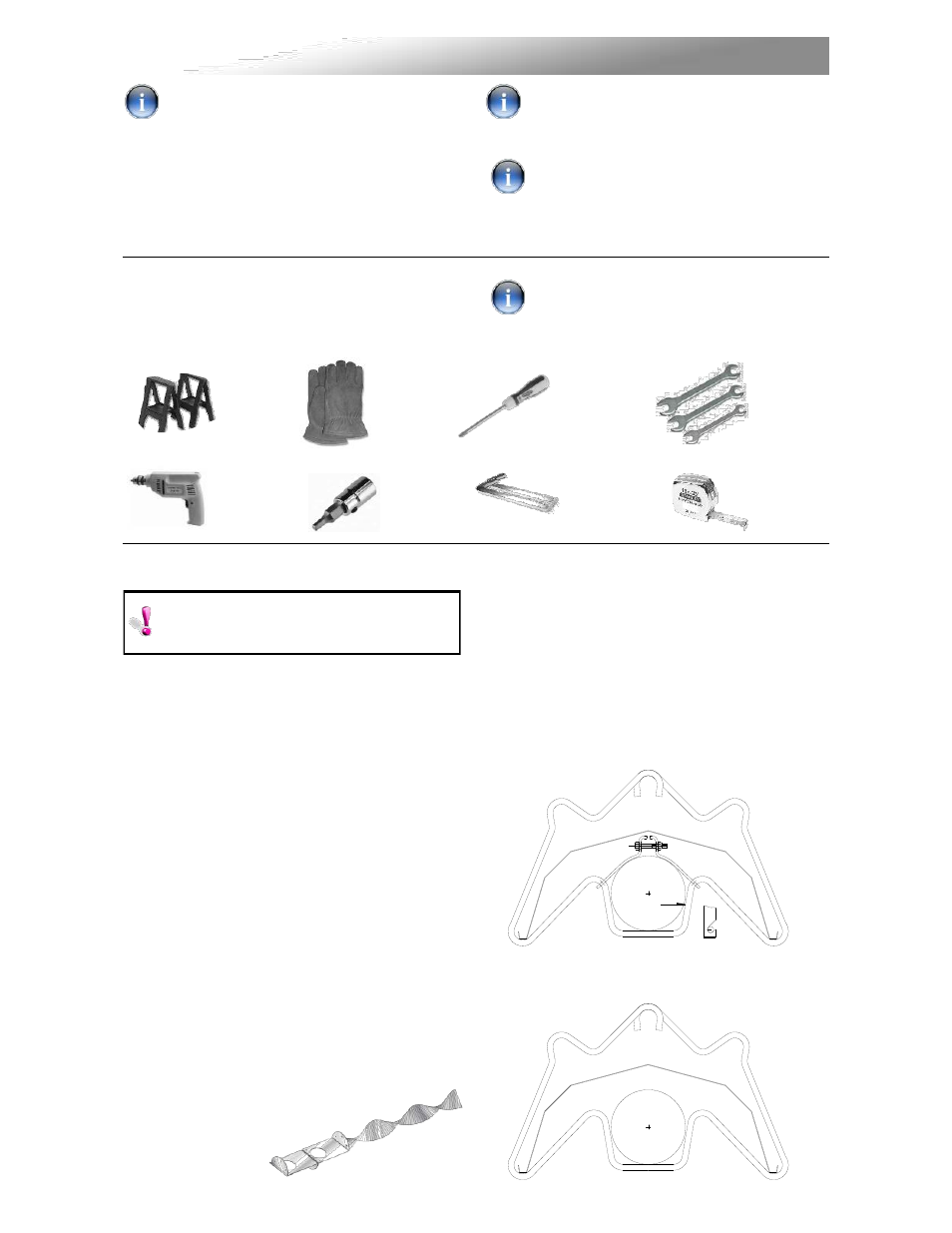
2.2.3 Brackets
There can be four types of brackets supplied
with these heaters:
2.2.3.1 Brackets for Indoor heaters
Type ‘H’ are suspension brackets with
tube straps.
Type ‘G’ are suspension brackets with
no tube straps.
2.2 Assembly Notes.
2.2.1 Tubes
Each heating unit has two types of emitter
tubes. For details of the tube types please refer
to the table (page 12 of this instruction
manual).
Identify and position tubes on saw horses. For
aesthetics it is advisable to position all tube
seams facing down. Position coupling
fastener so that these cannot be seen from
beneath the heater.
Mark out the position of the bracket centres
from the dimensions shown on the assemblers'
drawings.
Turbulators:
Ensure
that
the
correct
turbulator or burner insert is fitted, as this could
void your warranty if they are incorrectly fitted
or omitted when necessary.
2.2.2 Turbulators
(where fitted)
Insert turbulator into correct
tube as indicated in the
assembly drawings
PLEASE READ this section prior to
assembly to familiarize yourself with the
components and tools you require at the
various stages of assembly. Carefully open the
packaging and check the contents against the
parts and check list.
The manufacturer reserves the right to alter
specifications without prior notice.
Please ensure that all packaging is
disposed of in a safe environmentally
friendly way.
For your own safety we recommend the
use of safety boots and leather faced
gloves when handling sharp or heavy items. The
use
of
protective
eye
wear
is
also
recommended.
Phillips
Screwdriver
Saw
Horses
Leather
Faced
Gloves
Tape
Measure
5/16”
Drive
Cordless
Drill
Wrench
Set
2.1 Tools Required.
The following tools and equipment are advisable
to complete the tasks laid out in this manual.
Suitable alternative tools may be used.
Please read these assembly notes in
conjunction with the correct assembly
drawings (figs 9 to 17).
"A"
VIEW ON "A"
3/16” (5mm)
5/32” (4mm)
Allen
wrench
2. Assembly Instructions.