5 reflectors, 4 couplers – Reznor VPT Unit Installation Manual User Manual
Page 15
15
H
F
S
F
Burner
Assembly
Reflectors
2/0 GA CHAIN
(TWISTED LINK, PLATED)
NOTE.
HOOKS ARE TO
BE CLOSED UP
AFTER ASSEMBLY
EYE HOOK
the screw stop has butted up to the tube ends.
Using the 9/16” Wrench to tighten the bolts.
DO NOT OVERTIGHTEN.
Moving between the four bolts, tighten each
ensuring that equal pressure is applied to each
set pin in turn. Complete assembly by drilling
and screwing self tapping retention zip screws.
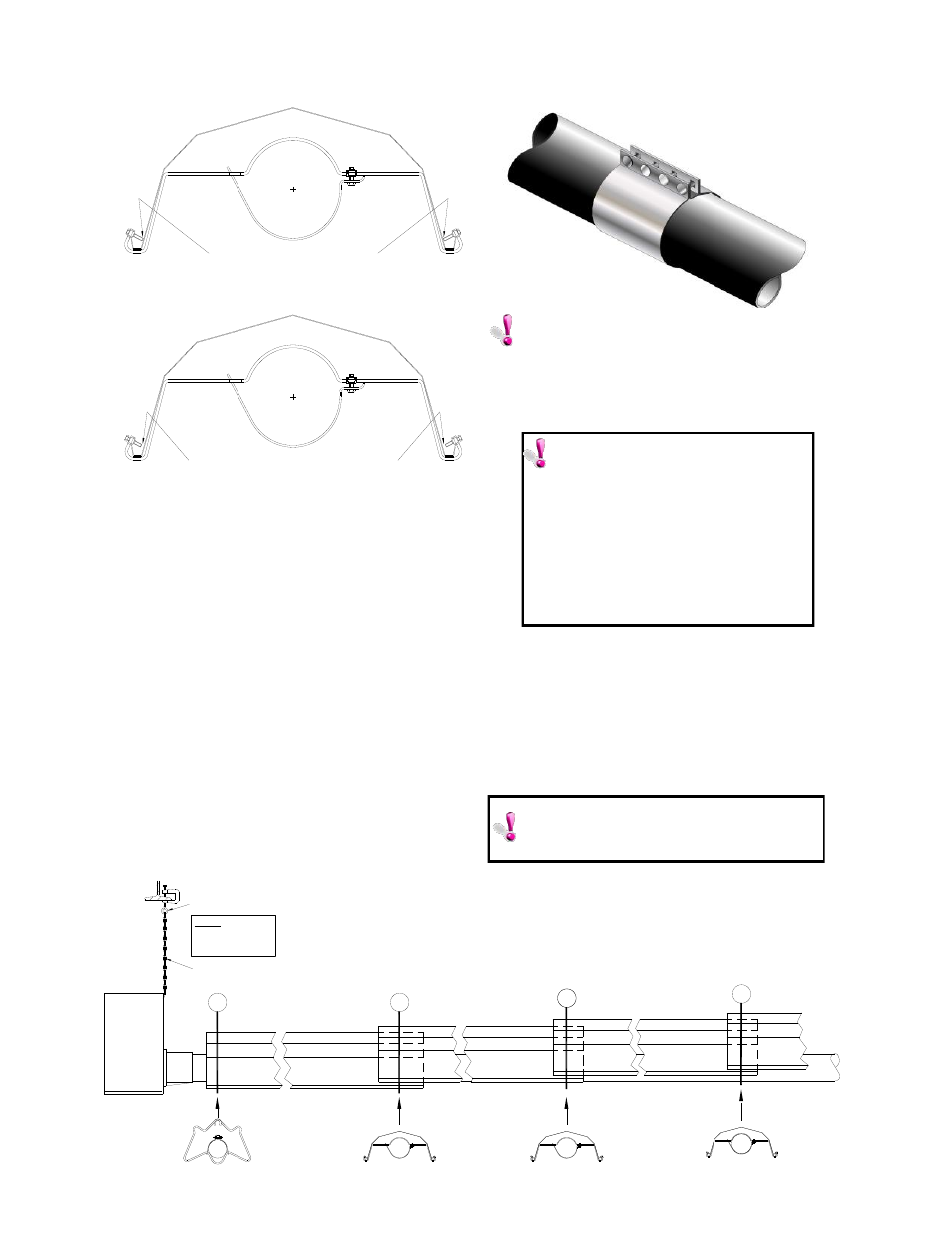
2.2.5 Reflectors.
After removing the protective plastic coating (if
fitted), slip the reflectors through the hanger
brackets until they overlap each other.
The first and second reflector are fixed at the
point F by a type F reflector support bracket and
are held in place by tightening the fixing screws.
Alternate fixings of further reflectors by type S
and type F reflector brackets and space as
indicated by individual assembly sheets.
Type ‘F’ are fixed reflector brackets.
Type ‘S’ are sliding reflector brackets.
Slip the suspension brackets onto the tube
assembly. The fixed suspension point ’H’
shown on the drawings are adjacent to the
burner and secures the first suspension bracket
to the tube with a tube strap. All other
suspension brackets ’G’ shown on the
drawings, have floating suspension points.
Reflectors are fixed at point ’F’ with a reflector
support bracket and reflectors are held in
position with fixing screws. Fixed and sliding
joints alternate along the heater at the
spacing's indicated on the individual heater
assembly sheets.
2.2.4 Couplers
The couplers are used for joining radiant tubes
and L bends.
Slide the coupler over the tube ensuring that
2 x SCREWS TIGHTENED TO FIX REFLECTOR
LEAVE 1/8" MIN. GAP TO ALLOW REFLECTOR TO SLIDE
At this point raise the tube assembly
into position and suspend from
previously fixed chains (Working Load
100lb), or attach to wall mounting
brackets. Wall mounting brackets must
support heater at an angle of inclination
of 45° ± 10°. Longer tube assemblies
may be raised in more than one
sub-assembly with final tube connection
made in the air.
All reflectors must be positioned/
attached to the brackets exactly as
detailed in the assembly drawings.