Reznor VPT Unit Installation Manual User Manual
Page 4
4
1.3 Clearance to Combustibles.
Minimum clearance to combustibles are shown in Table 1 below.
IMPORTANT: The stated clearance to combustibles represents a surface temperature of 90°F (50°C) above room
temperature. Building material with a low heat tolerance (such as plastics, vinyl siding, canvas, tri-ply, etc.) may be
subject to degradation at lower temperatures. It is the installer’s responsibility to ensure that adjacent materials are
protected from degradation.
* distance with end caps fitted.
Table 1 Clearance to Combustibles, inches (cm)
MODEL
A
B
B1
C1
C2
C3
D1
D2
E
60
74 (188) 29 (74) 41 (105) 6(16) / 3(8)* 8 (21)
22 (56)
8 (21)
14 (36)
10 (26)
80
74 (188) 29 (74) 41 (105) 6(16) / 3(8)* 8 (21)
22 (56)
8 (21)
14 (36)
10 (26)
100
74 (188) 32 (82) 41 (105) 6(16) / 3(8)* 8 (21)
22 (56)
8 (21)
16 (41)
10 (26)
125
74 (188) 39 (99) 47 (120) 6(16) / 3(8)* 8 (21)
22 (56)
20 (51)
18 (46)
10 (26)
150
74 (188) 39 (99) 48 (122) 6(16) / 3(8)* 8 (21)
22 (56)
20 (51)
18 (46)
10 (26)
170
86 (219) 48 (122) 48 (122) 6(16) / 3(8)* 11 (28)
22 (56)
20 (51)
20 (51)
10 (26)
200
86 (219) 48 (122) 48 (122) 6(16) / 3(8)* 11 (28)
22 (56)
20 (51)
20 (51)
10 (26)
Minimum clearance from the heater must be maintained from vehicles
parked below heater. In all situations, clearances to combustibles must be
maintained. Signs should be posted in storage areas to specify maximum stacking height to
maintain required clearance to combustibles. Such signs must either be posted adjacent to
the heater thermostats or in the absence of such thermostats in a conspicuous location.
Refer to mounting clearance tables.
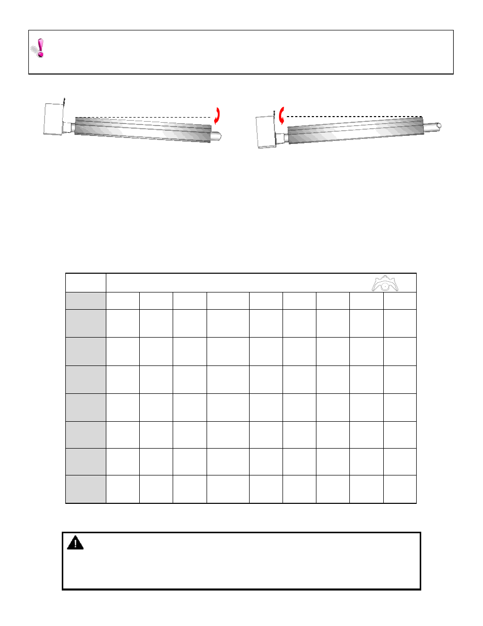
WARNING:
1/2”
ON U TUBE VARIANTS THE HEATER SHOULD SLOPE DOWNWARDS TOWARDS THE RETURN BEND AND
ON LINEAR VARIANTS SHOULD SLOPE DOWNWARDS TOWARDS BURNER BY APPROX. ½” FOR
HORIZONTAL INSTALLATIONS AS SHOWN BELOW (DIAGRAMS EXAGGERATED FOR CLARITY)
1/2”
U Tube heater side view
Linear heater side view
U bend
Outlet