Reznor VPT Unit Installation Manual User Manual
Page 7
7
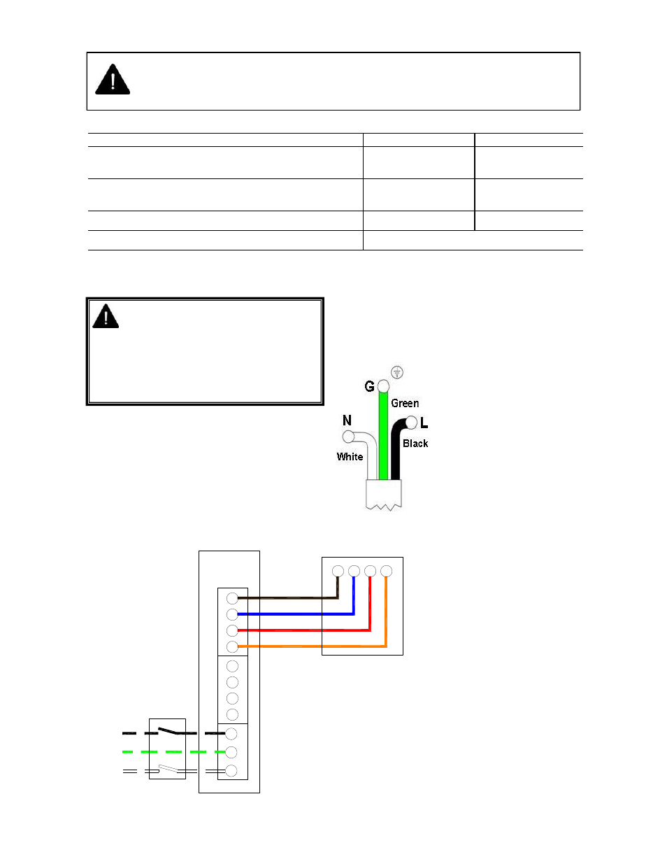
1.5 Electrical Connections
This appliance must be electrically grounded
Supply 120V 60Hz single phase.
Standard heater 0.16HP.
Current rating 1.2 amp max (inductive).
Fuse: external 3 amp.
Important: All electrical work should be done by a
qualified electrician in strict accordance with the
National Electrical Code ANSI/NFPA 70 or Canadian
Codes CSA C22.1.
The electrical supply to the heater
is by three wires: hot (Live),
neutral and ground connections.
Install in accordance with all state
& local codes.
Where alternative manufacturers
controls are used, please refer to
their instructions for installation
details.
Table 3 Gas Supply Pressures
WARNING: Before making electrical
connections, switch OFF the main
electrical disconnect. There may be more
than one disconnect switch. Lock out
and tag switch with a suitable warning
label. Electrical shock can cause
personal injury or death.
Figure 5. External Wiring Schematic.
CONNECTOR MUST BE INSTALLED IN A “U” CONFIGURATION. FOR HEATERS
UPTO 150,000 BTU/H, A 24” LONG CONNECTOR OF AT LEAST ½” ID MUST BE
USED. FOR HEATERS ABOVE 150,000 BTU/H, A 36” LONG CONNECTOR OF AT
LEAST ¾” NOMINAL ID MUST BE USED.
Gas Type
Natural Gas
LP/Propane Gas
Required Gas Pressure (in W.C) (60,000 TO 150,000
BTU)
5.0
11.0
Required Gas Pressure (in W.C) (170,000 TO
200,000 BTU)
7.0
11.0
Max Supply Pressure (in W.C)
14.0
14.0
Gas Supply
Connection ½” N.P.T thread
Notes:
Use 18/4 class 2 thermostat cable
between heater and thermostat.
Max. length @ 18 Awg (0.8mm²) =
100ft.
Only one burner can operate from
one thermostat as supplied.
When servicing heaters ensure
the electricity supply is isolated
from the mains supply.
120V AC supply is still present at
burner when the thermostat is
switched off.
F2
F1
R
C
W1
W2
24V AC
Terminals
(120V AC Fan
Terminals)
120V AC
Supply
24V AC 2-Stage
Thermostat (Ext.)
R
C
W1
W2
Burner 1
E
N
L
N
E
BL
BK
BK
G
W
KEY:
BK-BLACK
BL-BLUE
R-RED
O-ORANGE
G-GREEN
W-WHITE
R
O