Rev-A-Shelf 4WCTM-RM-2150DM-2 User Manual
Page 3
Inset Door Application Installation Note: Requires ½” minimum wall thickness
Step 1C
Locate the bottom of the side mounting bracket 15-3/4” (for 50 qt. frames) or 10-11/16”
(for 35 qt. frames) from the floor. The brackets also need to be flush with the front of the
cabinet wall. Use the #6 X 5/8” screws provided to attach the bracket to the wall. You may
also use additional #6 X 5/8” screws at the rear of the bracket for added stability.
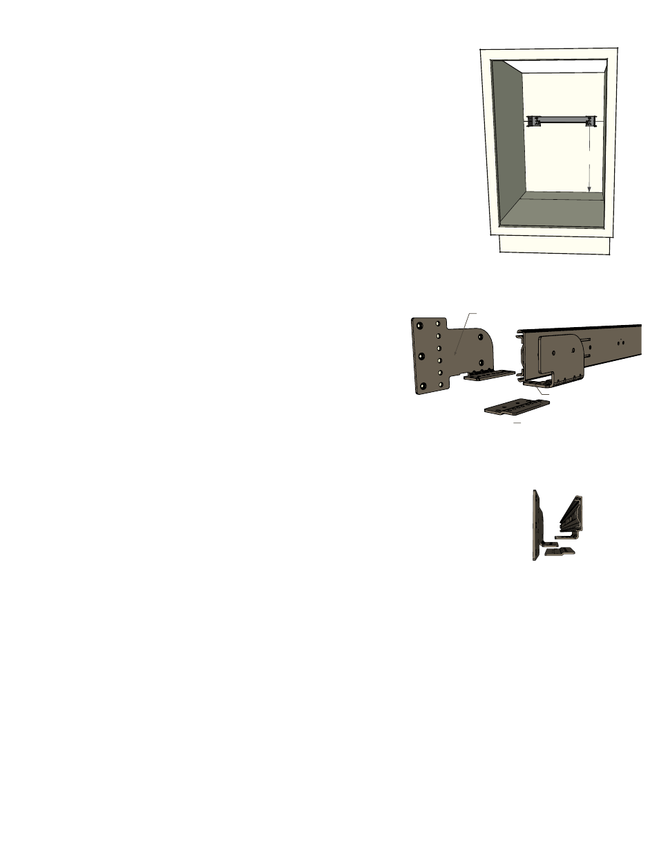
STEP 2C
Position the rear strap assembly centered on the back wall and elevated so that the center slot
of each rear socket is positioned at 17-15/16” (for 50 qt. frames) or 12-7/8”
(for 35 qt. frames) above the cabinet floor. (SEE FIGURE 2C)
Fasten the rear strap assembly to the rear cabinet wall using the (4) #8 x 5/8” pan head
screws provided. Make sure to center the strap assembly left to right according to the
opening of the cabinet. It is best to start with 2 screws in the center slots in
case adjustments are necessary.
Note: If rear of cabinet is thinner than 1/2”, a furring strip should be used
between the back wall and the mounting strap to ensure the rear mounting
strap is properly attached. Keep in mind the minimum depth required is
21-3/4” and is measured from the back of the door.
Step 3C
For inset door applications, the product member bracket, side mounting
bracket, and mending plate are necessary. (SEE FIG 3C)
Using the M5 hardware provided, attach the mending plate to the side mounting brackets using
hole locations “B”. The mending plate should go underneath the side-mounting bracket with the
numbers facing the floor and favoring the inside of the cabinet. (SEE FIGURE 3C)
Step 4C
Set the entire chassis in the cabinet. The rear of the slides should insert into the rear strap
assembly. This is a press fit and there will be resistance. The front product member bracket
should sit on top of the mending plate installed in step 3C.
Because there are so many variations of cabinet construction it is difficult to state a specific hole
pattern that will work best for your application. Center the chassis in the cabinet and confirm if
there are any of the labeled holes that can be used to mate the brackets together. If not, the outer
slots should provide enough width options to accommodate other sizes.
Using the remaining M5 hardware, assemble the product member bracket to the mending plate
and side-mounting bracket. PROCEED TO STEP 8
17-15/16” (50 qt.)
12-7/8” (35 qt.)
FIGURE 2C
FIGURE 3C
-Product Member Top
-Side Mount Brkt Middle
-Mending Plate Bottom