Figure 2b, Figure 3b – Rev-A-Shelf 4WCTM-RM-2150DM-2 User Manual
Page 2
Frameless Cabinet Installation
Step 1B Installing Side Mounting Brackets
Locate the bottom of the side mounting bracket 15-3/4” (for 50 qt. frames) or 10-11/16” (for 35 qt. frames) from the floor.
The brackets also need to be flush with the front of the cabinet wall. Move the bracket up or down to the nearest set of
system holes. Use the (3) M6.3 flat head euro screws for each side-mounting bracket with the corresponding 32mm sys-
tem hole. You may also use (2) #6 X 5/8” screws at the rear of the bracket for added stability. Measure the distance that
the bracket needed to move up or down to engage the system holes. If the bracket needed to move up, add the measured
dimension to 17-15/16” (for 50 qt. frames) or 12-7/8” (for 35 qt. frames). If the bracket
needed to move down subtract the dimension from 17-15/16” or 12-7/8”.
(USE THIS DIMENSION IN THE NEXT STEP)
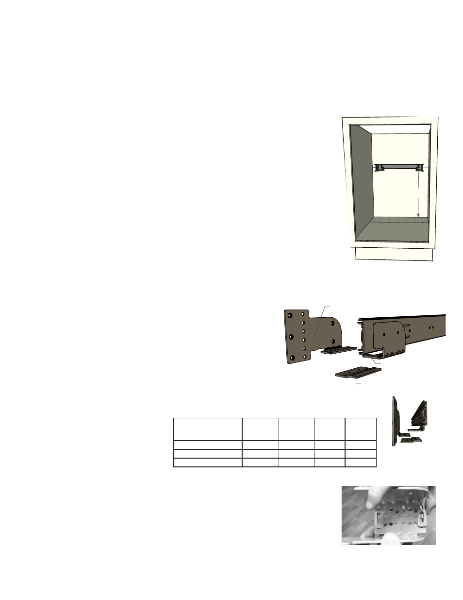
STEP 2B Attaching Rear Mounting Strap
Position the rear strap assembly centered on the back wall and elevated so that the center slot of
each rear socket is positioned at the newly formulated dimension. (For Example: For a
50 qt. frame - If the bracket needed to move up 1/16”, the center slot should be located at 18”
from the floor). If the side mount bracket did not need to move up or down from the 15-3/4”
simply use 17-15/16” as the center slot dimension on the rear strap assembly. (SEE FIGURE 2B)
Fasten the rear strap assembly to the rear cabinet wall using the (4) #8 x 5/8” pan head screws
provided. Make sure to center the strap assembly left to right according to the opening of the
cabinet. It is best to start with 2 screws in the center slots in case adjustments are necessary.
Note: If rear of cabinet is thinner than 1/2”, a furring strip should be used between the back wall and the mounting strap
to ensure the rear mounting strap is properly attached. Keep in mind the minimum depth required is 21-3/4” and is mea-
sured from the back of the door.
Step 3B Assembling Mending Plate to Side Mounting Brackets
For frameless cabinet applications, the product member bracket, side
mounting bracket, and mending plate are necessary. (SEE FIG 3B)
Please refer to table A for the proper hole alignment. If the table does not
apply to the cabinet in use, the outer slots will provide a fully adjustable
option to fit virtually any opening.
Using the M5 hardware provided, attach
the mending plate to the side mounting
brackets using hole locations “B”. The
mending plate should go underneath the
side-mounting bracket with the numbers
facing the floor and favoring the inside of
the cabinet. (SEE FIG 3B)
Step 4B
Set the entire chassis in the cabinet. The rear of the slides should insert into
the rear strap assembly. This is a press fit and there will be resistance.
The front product member bracket should sit on top of the mending plate installed in step 3B.
Step 5B
Using the remaining M5 hardware, assemble the product member bracket to the mending plate and
side-mounting bracket according to TABLE 1. PROCEED TO STEP 8
17-15/16” (50 qt.)
12-7/8” (35 qt.)
FIGURE 2B
-Product Member Top
-Side Mount Brkt Middle
-Mending Plate Bottom
FIGURE 3B
.75” Wall Example
TABLE A
SIDE MOUNTING
BRACKET HOLE
LOCATION
PRODUCT
MEMBER HOLE
LOCATION
RIGHT
MENDING
PLATE HOLE
LOCATION
LEFT
MENDING
PLATE HOLE
LOCATION
Frameless with .75” Wall
B
A
2 & 5
4 & 7
Frameless with .708” (18 mm) Wall
B
D
1 & 8
1 & 8
Frameless with .625” Wall
B
B
3 & 6
3 & 6