Potter PFC-5000 Series User Manual
Page 35
31
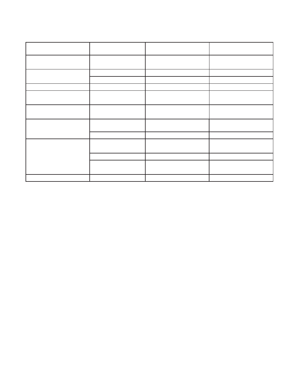
Table 4: Confi guration DIP Switch Functions on ZA-42 Module
Function
DIP Switch on ZA-42
Module
Switch "Off"
Switch "On"
NAC Circuit #3
Audible Device (Bell) Only
Switch 6, #1
Silenceable
Non-Silenceable
NAC Circuit #4
Audible or Visual Device
Switch 6, #2
Silenceable
Non-Silenceable
Switch 6, #3
Audible Device (Bell)
Visual Device (Strobe)
Not Used
Switch 6, #4
-----------------
-----------------
Initiating Circuit #5
Alarm Only
Switch 5, #1
Normal Alarm
Verifi ed Alarm
Initiating Circuit #6
Alarm Only
Switch 5, #2
Normal Alarm
Verifi ed Alarm
Initiating Circuit #7
Alarm or Waterfl ow
Switch 5, #3
Normal
Verifi ed Alarm / Retarded
Waterfl ow
Switch 5, #4
Alarm
Waterfl ow
Initiating Circuit #8
Alarm or Supervisory
Switch 5, #5
Normal
Verifi ed Alarm
(No effect on Supervisory)
Switch 5, #6
Alarm
Supervisory
Switch 5, #7
Non-Latching Supervisory (No
effect on Alarm)
Latching Supervisory
(No effect on Alarm)
Not Used
Switch 5, #8
-----------------
-----------------
Note:
After you change any confi guration switches, perform a system hard reset or power off/on sequence. If this is not done,
•
then a Switch Tamper Trouble will occur. Perform a hard reset by pressing SW0 push button switch on back of main
panel pcb.
Do not use retard operation with any external retarding device; maximum retard may not exceed 90 seconds.
•
When confi guring the ZA-42, keep in mind the following information:
Only NAC Circuit #4 may be confi gured for visual devices.
•
If Initiating Circuit #7 is confi gured as waterfl ow, the corresponding verifi ed selection becomes a retard selection.
•
If Initiating Circuit #8 is confi gured as alarm, the corresponding latching selection has no effect.
•
If Initiating Circuit #8 is confi gured as supervisory, the corresponding verifi ed selection has no effect.
•
The selection of Class A/B (Style Z/Y) NAC circuits is only a matter of how they are wired. See connection information on
•
page 15.
If Class A (Style D) initiating circuits are selected, JW2 and JW3 jumpers must also be set. Class B
•
initiating circuits
5 and 6
combine to create Class A Circuit #3, and Class B initiating circuits 7 and 8 combine to create Class A Circuit #4. DIP
switches for circuits 5 to 8 are ignored, and led indicators for circuits 5 to 8 are non-functional.