Potter PFC-5000 Series User Manual
Page 34
30
When confi guring the PFC-5000 main board, keep in mind the following information:
Only NAC circuit 2 may be confi gured for visual devices.
•
If initiating circuit 3 is confi gured as waterfl ow, the corresponding verifi ed selection becomes a retard selection.
•
If initiating circuit 4 is confi gured as alarm, the corresponding latching selection has no effect.
•
If initiating circuit 4 is confi gured as supervisory, the corresponding verifi ed selection has no effect.
•
The selection of Class A/B (Style Z/Y) NAC circuits is only a matter of how they are wired. See connection information on
•
page 13.
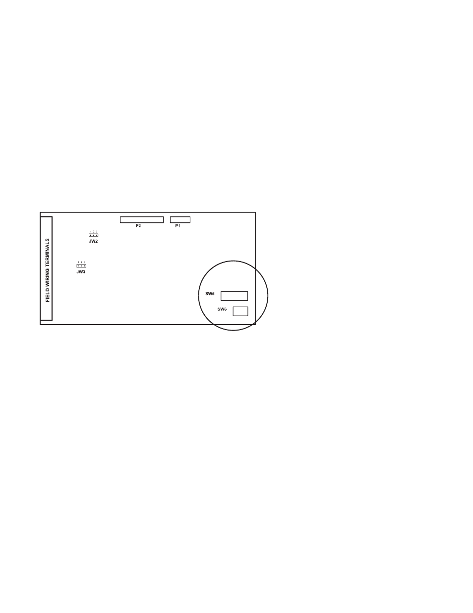
If Class A (Style D) initiating circuits are selected, JW1 and JW2 jumpers must also be set. Class B initiating circuits 1 and 2
•
combine to create Class A Circuit #1, and Class B initiating circuits 3 and 4 combine to create Class A Circuit #2. DIP
switches for circuits 3 and 4 are ignored except for an PFC-5004E with a ZA-42 Adder Module. LED indicators for circuits
3 and 4 are non-functional except for an PFC-5004E with a ZA-42 Adder Module.
ZA-42 Module
On the ZA-42 Zone Adder Module the DIP switches are located on the bottom right-hand corner.