Module settings, Main fire alarm module, Figure 5: main fire alarm module – Potter PFC-5000 Series User Manual
Page 13
9
Module Settings
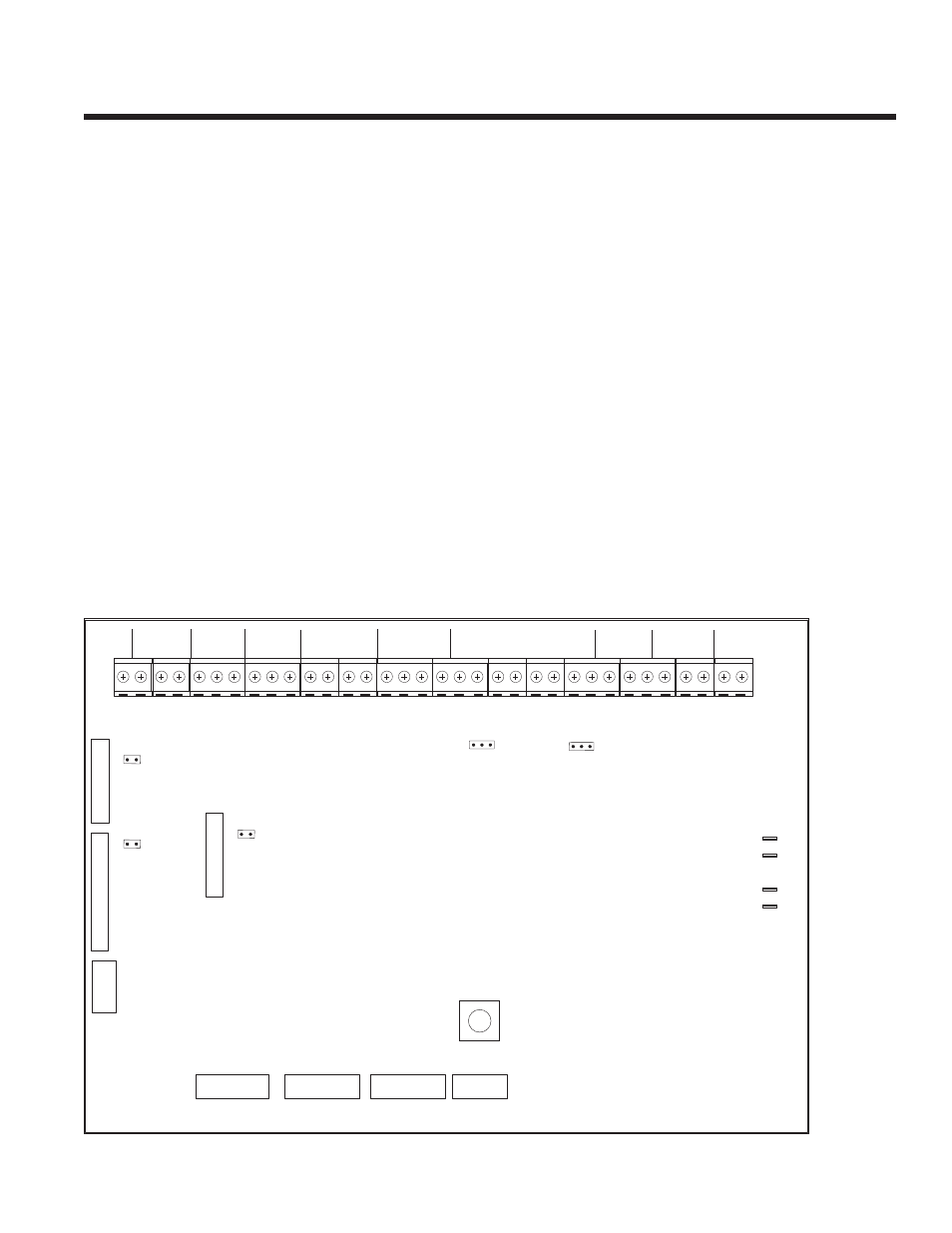
Main Fire Alarm Module
Class A / B Selection
On the PFC-5002, PFC-5004, PFC-5008 and PFC-5004E, to select Class B (Style B) move JW1 & JW2 to position “B.” To
select Class A (Style D) move JW1 & JW2 to position “A”.
Note: The Class A/B selection affects all initiating circuits, and must be used with the correct Confi guration DIP switch 9 #6. See
Table 3 on page 29.
Zone Adder Module: On an PFC-5004E only, remove the jumper on JW4 if a ZA-42 Zone Adder Module is installed. The zone
adder module is plugged into P6 & P7.
Relay Module: Remove the jumper on JW3 if an ARM-4 or ARM-8 Relay Module is installed. The relay module is plugged into
P1.
Digital Communicator: Remove the jumper on JW6 if a UDACT-9100 Digital Communicator is installed. The digital
communicator is plugged into P8.
City Tie: Remove the jumper on JW6 if a PR-5100 City Tie is installed. The City Tie is plugged into P8.
Battery: Connected to P2(+) & P3(-) via the factory installed cables.
Transformer: Factory wired to P4 & P5, do not disconnect.
SW9,11,13: Confi guration DIP switches.
Figure 5: Main Fire Alarm Module
P6
P6
SW13
SW13
A
B
JW2
JW2
P3
P3
A
B
BATT
BATT+
P4
P4
P5
P5
P2
P2
BATT
BATT-
GND
GND
XMFR
XMFR
XMFR
XMFR
JW1
JW1
P7
P7
P8
P8
JW4
JW4
JW3
JW3
JW6
JW6
SW11
SW11
SW9
SW9
P1
P1
SUPV
SUPV
RLY
LY
C
O
M
-
C
O
M
+
T
R
B
T
R
L
N
O
N
C
C
O
M
ALM
ALM RLY
LY
N
O
N
C
C
O
M
TBL
TBL RLY
LY
N
O
N
C
C
O
M
B- A- A+ B+
B- A- A+ B+ B- A- A+ B+
B- A- A+ B+
NA
NAC2 (IND2
C2 (IND2) N
) NAC
AC1 (IND1
1 (IND1)
- + - + - + -
- + - + - + - +
INI4
INI4
INI3
INI3
INI2
INI2
INI1
INI1
S -
S - +
RS-485
RS-485
-
- +
4 WIRE
4 WIRE
MANU
MANUFA
FACTURER US
CTURER USE
P1
P1
P1
P1