Potter PFC-5000 Series User Manual
Page 14
10
Zone Adder Module (Model ZA-42)
Figure 6: ZA-42 Zone Adder Module
Class A / B Selection: JW2 & JW3 are connected from 1 to 2 for initiating circuit Class B (Style B) operation, and from 2 to 3
for Class A (Style D) operation.
Note:
The Class A/B selection affects all initiating circuits, and must be used with the correct Confi guration DIP switch 9 #6.
P1 & P2: Connections to P7 & P6 respectively on the main fi re alarm board.
SW5,6: Confi g DIP switches.
P1
S
L
A
NI
M
R
E
T
G
NI
RI
W
D
L
EI
F
P2
SW5
2 3
1
JW3
SW6
2 3
1
JW2
A LM
K1
RLY1
RM
-208
/
R
M
-20
4
RE
L
A
Y
MO
D
UL
E
RLY2
RLY3
RLY4
RLY5
RLY6
RLY7
RLY8
NO
NO
NC
CO
M
NO
NC
CO
M
NO
NC
CO
M
CO
M
NO
NC
CO
M
NO
NC
CO
M
NO
NC
NC
CO
M
NO
NC
CO
M
K2
K3
K4
K5
K6
K7
K8
JW
1A
SUPV
JW 1
JW 2
JW 3
JW 4
P1
JW 5
JW 6
JW 7
JW 8
JW1.2
A LM
JW
2
A
SUPV
JW2.3
A LM
JW
3
A
SUPV
JW 3.4
A LM
JW
4
A
SUPV
JW4.5
A LM
JW
5
A
SUPV
JW5.6
A LM
JW
6
A
SUPV
JW6.7
A LM
JW
7
A
SUPV
A LM
JW
8
A
SUPV
JW7.8
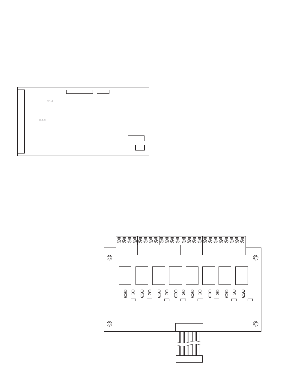
Relay Modules (Models ARM-4 or ARM-8)
Figure 7: ARM-4 or ARM-8 Relay Adder Module (Zone Operated)
P1: Connect to P1 on the main fi re alarm board.
By the factory setting, the four or eight relays are controlled by initiating circuits 1 to 8 respectively. This is confi gured by
selecting:
JW1:
•
Initiating Circuit #1 controls Relay #1.
JW2
•
: Initiating Circuit #2 controls Relay #2.
JW8:
•
Initiating Circuit #8 controls Relay #8.
Alternately, each relay may be set as a Common Alarm or Common Supervisory Relay by removing the jumper from JW1 to
JW1A, etc. These jumpers have two
positions to select Alarm or
Supervisory each.
JW1A:
•
Alarm or supervisory
control for Relay #1.
JW2A:
•
Alarm or supervisory
control for Relay #2.
JW8A:
•
Alarm or supervisory
control for Relay #8.
Finally, there are jumpers JW1.2,
JW2.3, up to JW7.8 that allow a relay to
have the same control as an adjacent
relay. For example, starting with the
factory default setting, moving the
jumper from JW2 to JW1.2 will make
both relays 1 & 2 operate with Initiating
Circuit #1.Contact Potter Technical
Support for assistance if required.