System confi guration, Main fire alarm board – Potter PFC-5000 Series User Manual
Page 32
28
System Confi guration
Main Fire Alarm Board
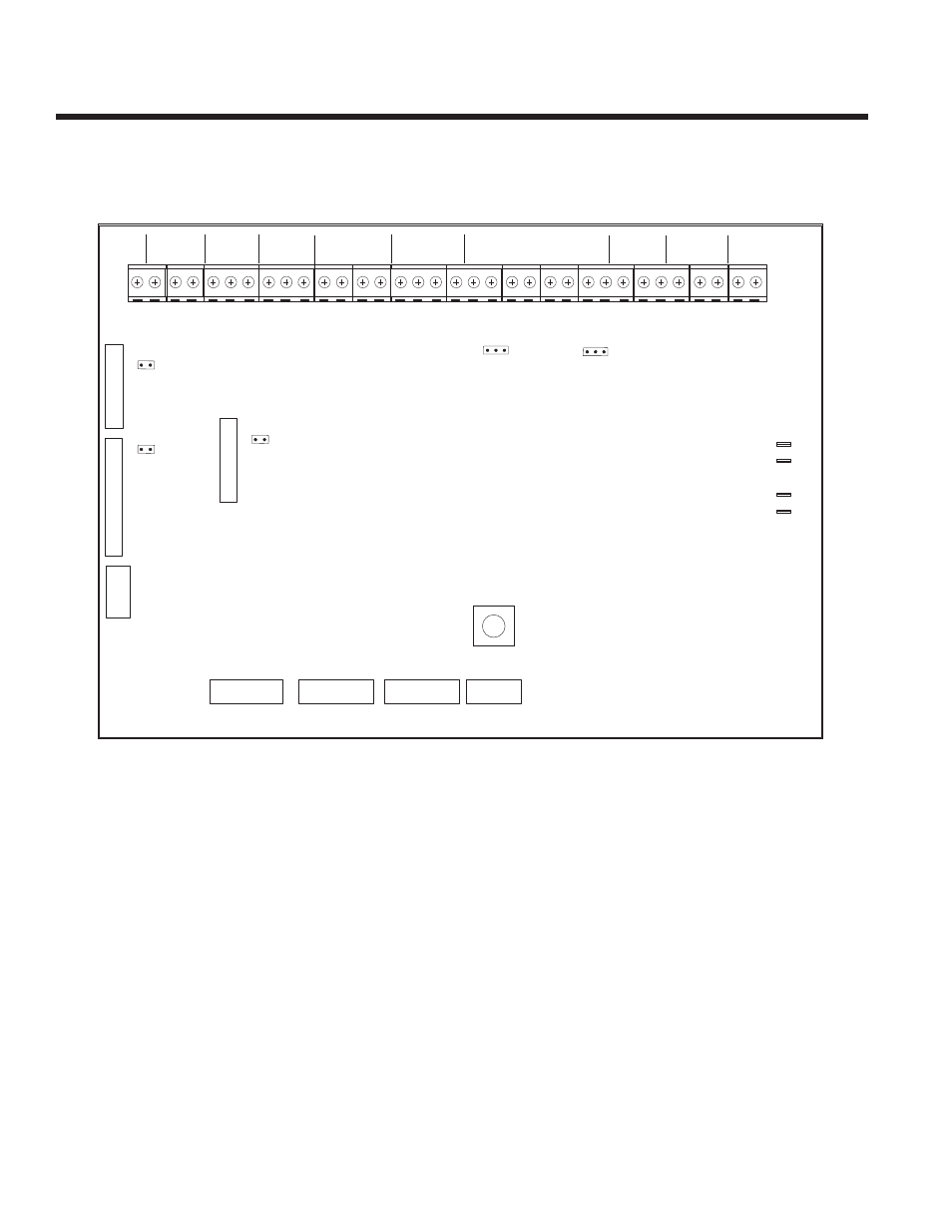
Confi guration of the PFC-5000 Series is accomplished simply by DIP Switch Settings on the Main Fire Alarm Board. For DIP
Switches, 0 = switch “off”, 1 = Switch “on’). The DIP switches are located on the bottom left side of the main fi re alarm board.
P6
P6
SW13
SW13
A
B
JW2
JW2
P3
P3
A
B
BATT
BATT+
P4
P4
P5
P5
P2
P2
BATT
BATT-
GND
GND
XMFR
XMFR
XMFR
XMFR
JW1
JW1
P7
P7
P8
P8
JW4
JW4
JW3
JW3
JW6
JW6
SW11
SW11
SW9
SW9
P1
P1
SUPV
SUPV
RLY
LY
C
O
M
-
C
O
M
+
T
R
B
T
R
L
N
O
N
C
C
O
M
ALM
ALM RLY
LY
N
O
N
C
C
O
M
TBL
TBL RLY
LY
N
O
N
C
C
O
M
B- A- A+ B+
B- A- A+ B+ B- A- A+ B+
B- A- A+ B+
NA
NAC2 (IND2
C2 (IND2) N
) NAC
AC1 (IND1
1 (IND1)
- + - + - + -
- + - + - + - +
INI4
INI4
INI3
INI3
INI2
INI2
INI1
INI1
S -
S - +
RS-485
RS-485
-
- +
4 WIRE
4 WIRE
MANU
MANUFA
FACTURER US
CTURER USE
P1
P1
P1
P1