Finished installation – Neuspeed 65.10.79 User Manual
Page 2
NEUSPEED® • 3300 Corte Malpaso • Camarillo, CA 93012 • 805.388.7171 • 805.388.0030 FAX •
• Visit us on the web…
http://www.neuspeed.com
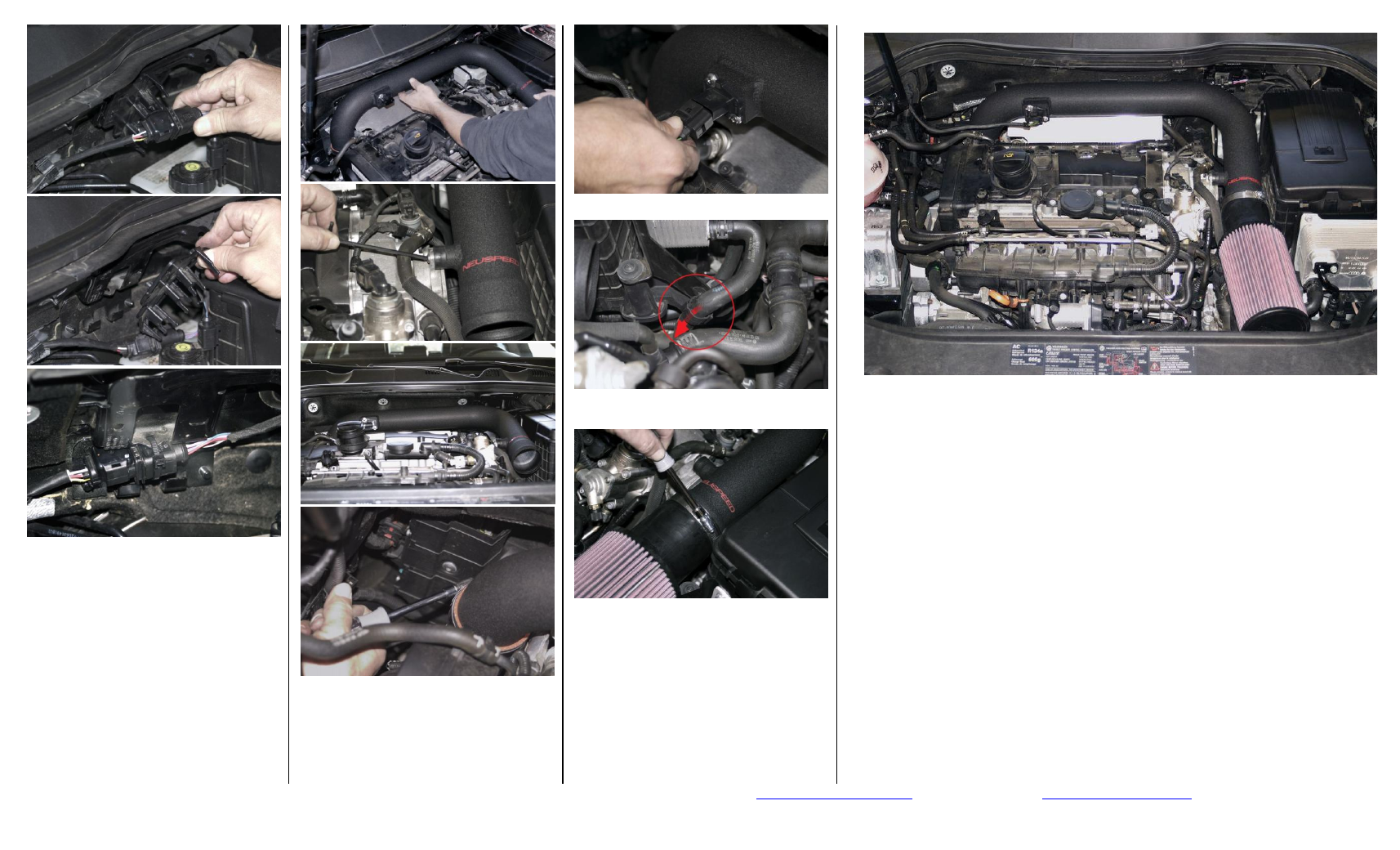
11. Remove 0
2
sensor connector from clip at
firewall. Pull off plastic harness clip
from firewall. Wire-tie 0
2
sensor
harness to firewall bracket as shown.
12. Install NEUSPEED intake pipe onto turbo
inlet with #44 clamp supplied and
attach rubber isolator mount to ear on
end of cylinder head with M6x10mm
screw. Intake pipe should be positioned
at an upward angle toward brake fluid
reservoir for engine torque clearance,
now tighten hose clamp and M6 screw.
13. Attach MAF electrical connector.
14. Slide coolant hose down in retaining
clamp just before molded bend in hose.
15. Install filter onto end of intake pipe and
tighten clamp. Position NEUSPEED logo
on end of filter horizontally for correct
positioning.
16. Double check installation and tightness
of all connections. PLEASE TEST DRIVE
CAREFULLY.
FINISHED INSTALLATION
Copyright 2008, NEUSPEED
®
. All rights reserved. Reproduction in whole or in part prohibited.
DOC. 65.10.79 Rev. 03.19.08