Bolt identification and location photo – Neuspeed 15.02.25.4 User Manual
Page 2
NEUSPEED® • 3300 Corte Malpaso • Camarillo, CA 93012 • 805.388.7171 • 805.388.0030 FAX •
• Visit us on the web…
http://www.neuspeed.com
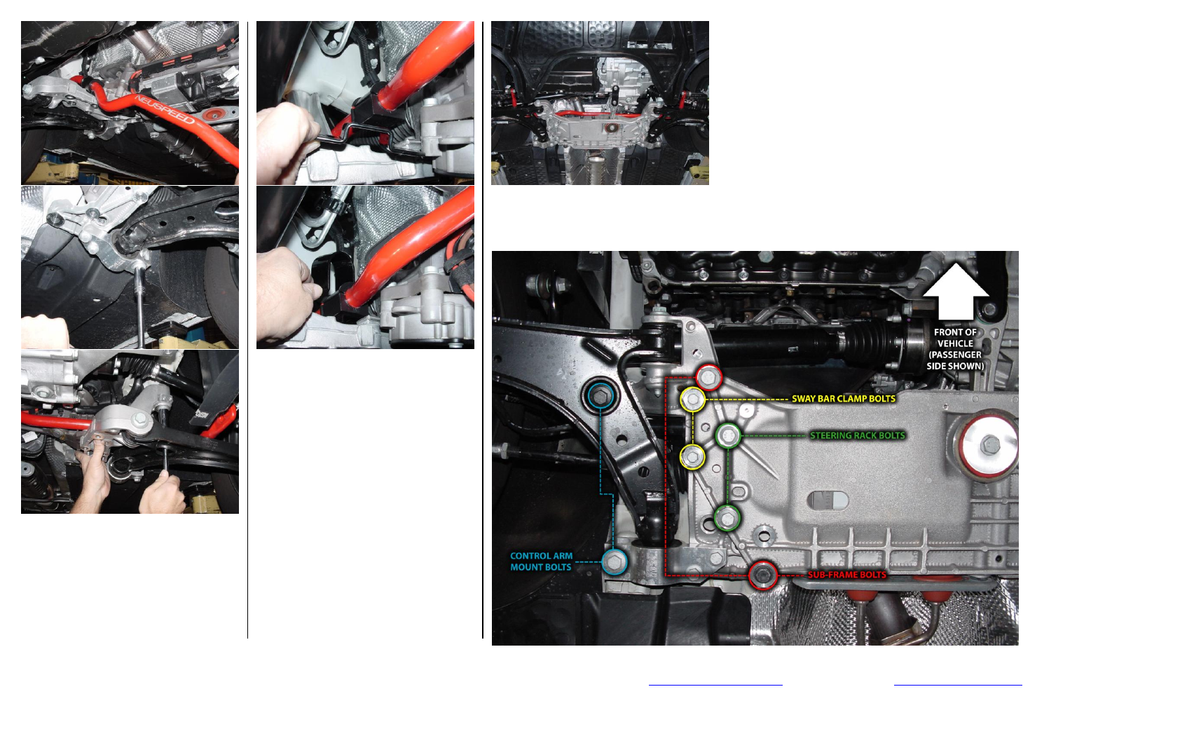
BOLT IDENTIFICATION AND LOCATION PHOTO
10. Install
NEUSPEED
anti-roll
bar
passenger’s side first. Lift up aluminum
control arm mount and guide steering
rack alignment bushings onto mount.
Hand-tighten bolts.
11. Attach original end-links to anti-roll bar
with original nuts and tighten.
12. Put into position urethane bushing base
and “U” bracket.
13. Reinstall aluminum sub-frame, start all
bolts by hand and use WD-40 or
equivalent on bolt threads. When
installing anti-roll bushing clamp bolts,
make sure bolts go thru bushing base
then thread into nuts on “U” bracket.
First; line up pen marks on uni-body
and tighten control arm mounting bolts,
then evenly tighten all other bolts.
TORQUE SPECS:
Control arm mount & sub-frame: 18mm hex
bolts 70Nm (52 Ft.-Lbs.) + 1/4 turn
Steering rack: 16mm hex bolts 50Nm (37
Ft-Lbs.) + 1/4 turn
Anti-roll bar clamp bolts: 13mm hex bolts
20Nm (15 Ft-Lbs.) + 1/4 turn
Torque arm mount at transmission: 16mm
hex bolts 40Nm (30 Ft-Lbs.) + 1/4 turn
14. Reinstall plastic wire guide, torque arm
bolts and engine splash pan.
15. Double-check complete installation and
TEST DRIVE CAREFULLY!
©Copyright 2011, NEUSPEED
®
All rights reserved.
Reproduction in whole or in part prohibited.
DOC.15.02.25.4 Rev. 03.24.11