MF Digital Spectrum 2 Thermal (Rev: 03/05/01) User Manual
Page 30
Spectrum2 Printer Operator’s Guide
Document Revision: 100102
29
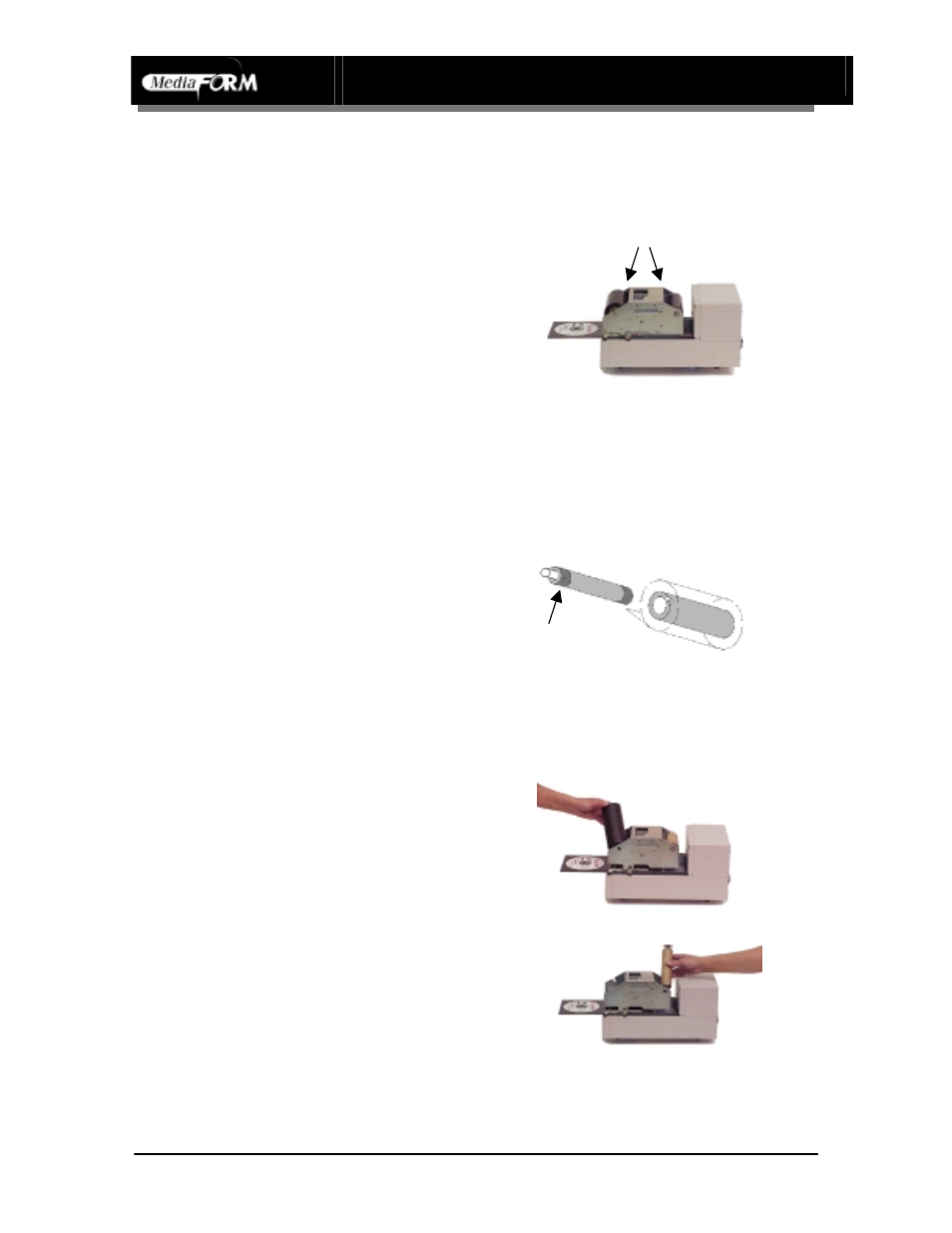
Printer Ribbon Installation Chart – Part 1
Remove Cover
•
Remove the top cover by carefully
lifting and pulling forward. Remove
used ribbon from printer
Note: Ribbon rollers are held in place
by locking clips secured by
thumbscrews. Loosen but do not
remove thumbscrews to adjust roller
clips.
Load Ribbon Rollers
•
Insert the supply ribbon core onto
the silver supply spindle (shown)
•
Insert the take up core on to the gray
take up spindle
Note: Ribbon roller has a metal pin that
fits into a notch in the ribbon core.
There are two pin positions for different
length ribbons.
Putting Rollers in printer
•
Supply Roller is placed into area at
the front of the printer.
Note: Supply Roller has metal shaft
with square end that fits into square
hole in printer frame
•
Take up core is placed in area at in
the middle of the printer.
Note: Take up core Roller has metal
shaft with round end that fits into round
hole in printer frame
Locking clips
Pin