Ee-sim user guide – Maxim Integrated EE-Sim User Manual
Page 27
page
27
EE-Sim User Guide
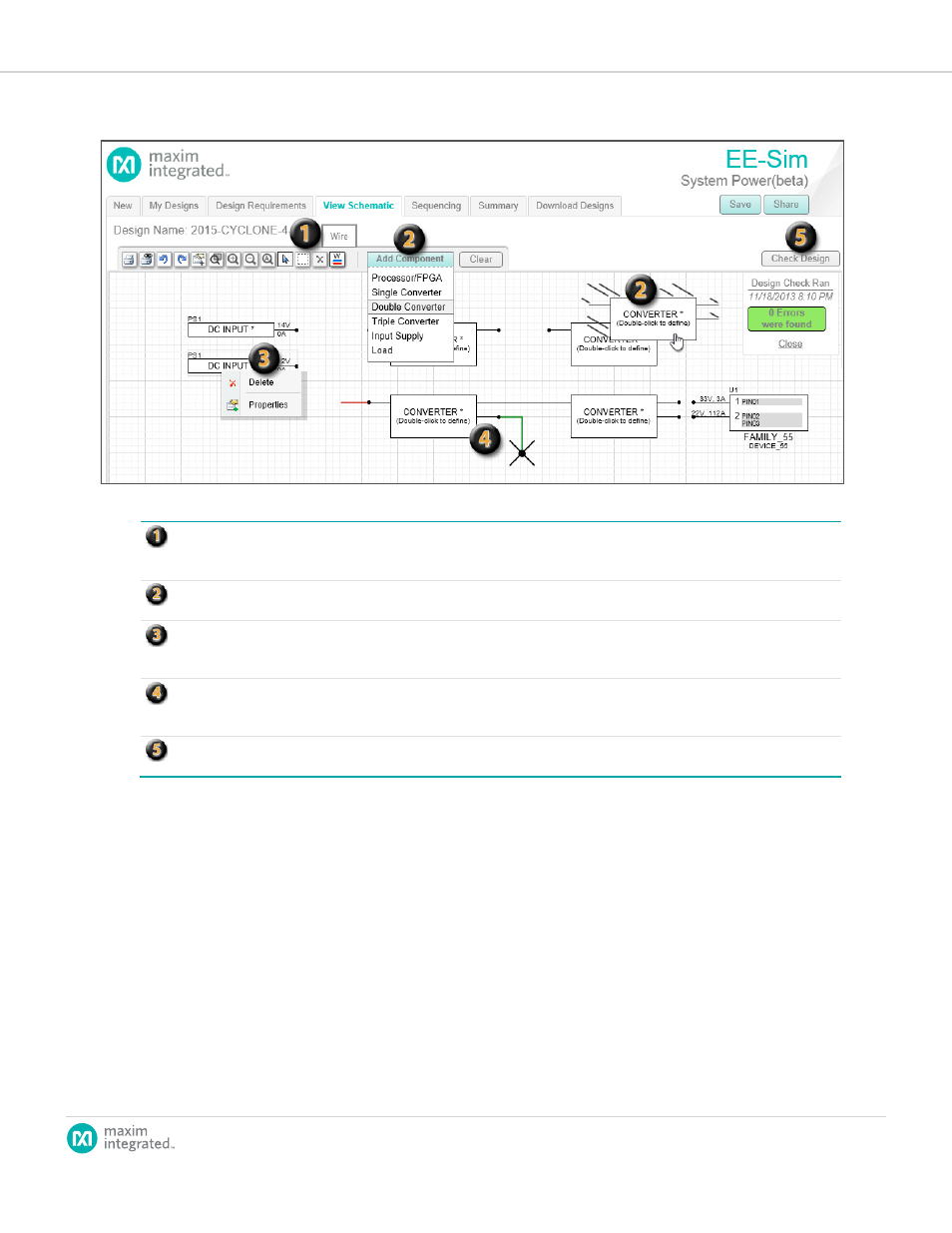
Toolbar:The top of the window shows a toolbar you can use to access tool buttons for familiar commands. Youwill recognize
icons for the print, undo, redo, zoom, select, delete, and wire commands. To refresh your memory, position your mouse over
an icon to view its functional name in a tooltip.
Add Component: When you click this button, a menu appears.Choose acomponent. Slowly move your mouse down to
position the new component in the grid.
Right-Click Menu: Instead of clicking a component first and then clicking the Delete toolbar butt on, you can right-click the
component and choose Delete from a shortcut menu. Instead of double-clicking a component to view its properties, you can
right-click and choose Properties.
Connection Wires: When positioning your mouse over a connection point, it changes to the X-shaped wire cursor.You can
connect a new green line to another line or point. Red lines represent incomplete connections. Complete connecti ons appear
as straight line segmentsor 90° connected line segmentswith no points.
Check Design: Click Check Designtodetermine if theconverters are properly sized for the loads they are supporting. When
you navigate away from theView Schematicpage, EE-Sim automatically checks your design and reports anyvalidationerrors.