2 next steps, 4 .2 next steps, Ee-sim user guide – Maxim Integrated EE-Sim User Manual
Page 25
page
25
EE-Sim User Guide
6. Complete one or more rows in the power requirements table:
a. In the
Pin Name field, enter the unique identifier for each pin (for
example, VCCO).
b. In the
Group field, enter an integer number. To combine rails with
the same voltage, enter the same group number for those rails.
c. In the
Voltage (V) field, enter the voltage.
d. In the
Ireq (A) field, enter the amperage.
e. In the
Supply Tolerance field, adjust the tolerance threshold if
you require a value greater than or less than the default value of
±2.5%.
f. To delete a row, click
Delete.
g. To add settings for a new pin, click
+ Add Row.
7. Click
Preview Device to view the rails and pins for your device.
a. Any missing values in the table appear with a red border to alert
you to finish entering your design requirements.
b. Correct any conflicting voltage values if you assigned a shared group
number to rows with different voltages. Enter the same voltage for
each row in the group.
8. Examine the preview image and, if necessary, adjust any values.
9. In the
DC Input Requirement section, adjust the default voltage in the
Supply Voltage field.
10. Click
Create Design.
11. Click
Save to save your changes.
4.2 Next Steps
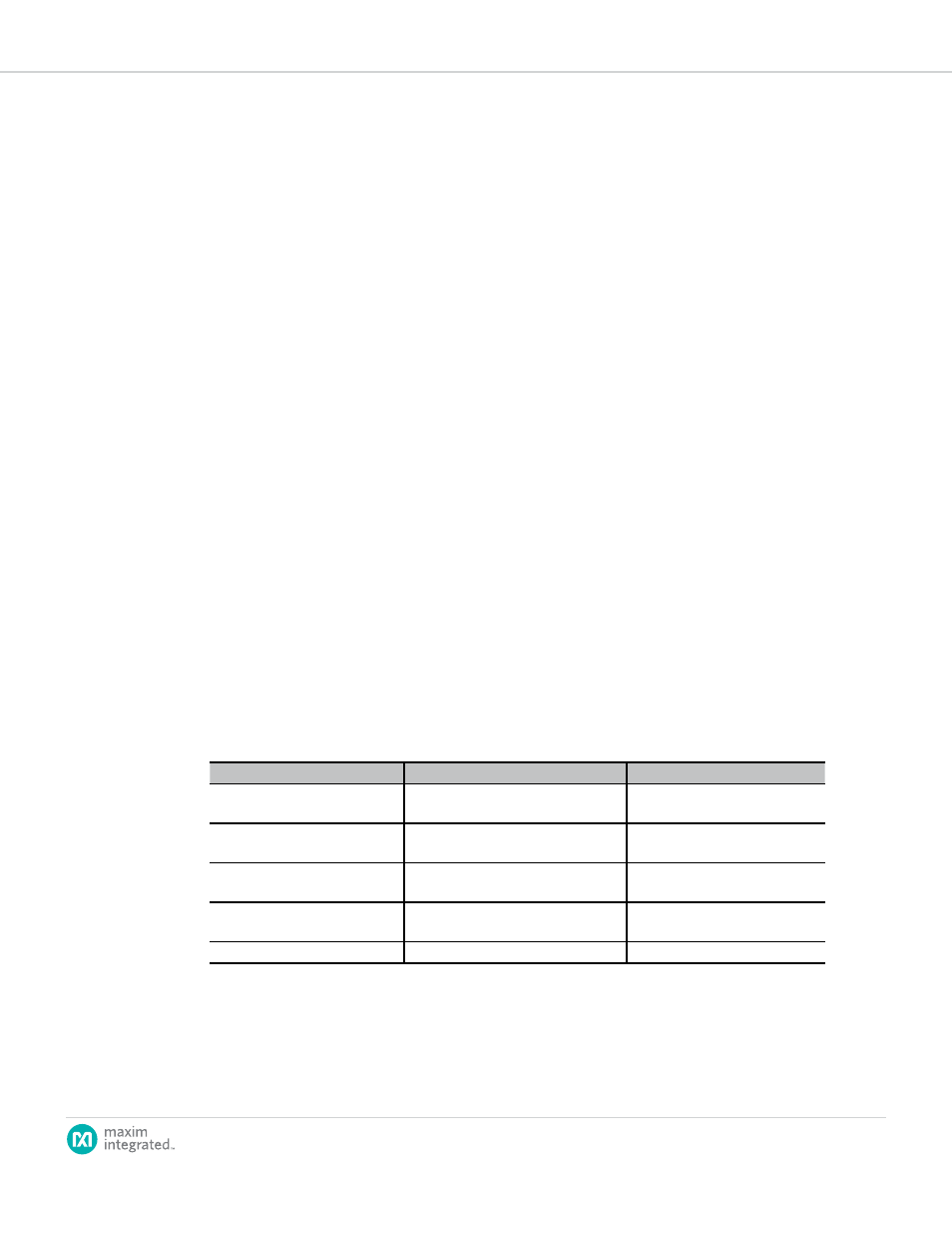
Congratulations! You generated a schematic and saved your design. As a summary,
you can now perform one or more of the following tasks:
Task
Step
Learn More
To edit your design
Click the
Design Requirements tab.
4.1 Creating New System Power
Processor Designs
To edit your schematic
Click the
View Schematic tab.
4.3 Modifying System Power
Schematics
To configure sequencing and
group/rail assignments:
Click the
Sequencing tab.
4.4 Sequencing
To complete the design, view a
summary, and download a BOM
Click the
Summary tab.
4.5 Generating a Summary Page
and BOM (System Power)
To download designs
Click the
Download Designs tab.
7.4 How to Download a Schematic
Note: You are not required to visit every tabbed page in EE-Sim.