3 generating a schematic and saving your design, 4 next steps, Ee-sim user guide – Maxim Integrated EE-Sim User Manual
Page 17
page
17
EE-Sim User Guide
3.3 Generating a Schematic and Saving Your Design
In the two previous procedures, you selected a part and entered your design
requirements. Follow these steps to generate a schematic and save your new
design.
1. When all your values have been entered, click
Create Design.
2. EE-Sim performs a complex set of calculations to design a circuit that
meets your requirements. A visual representation of your design appears
on the
Schematic page. Where practical, the tool also identifies specific
supporting components.
3. Click the
Save button to save your design. In the Save Your Design
window:
a. In the
Design Name field, enter a unique name to differentiate this
design from your other designs as well as the shared designs of
other users.
b. In the
Design Description field, enter a short description of the
design to remind you later of its purpose. The description is also
helpful for any recipients if you decide to share the design.
c. Click
Save.
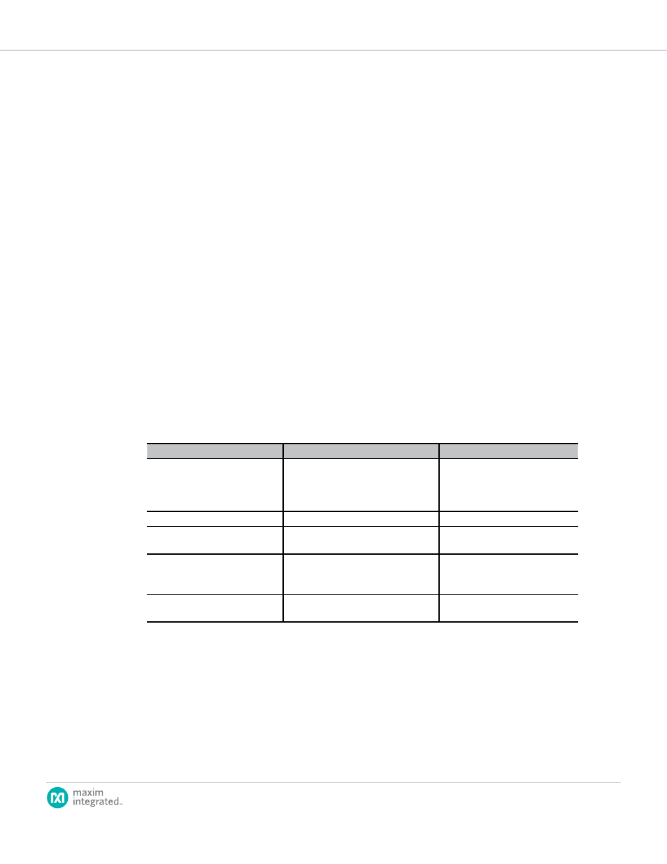
3.4 Next Steps
Congratulations! You’ve generated a schematic and saved your design. You
can now perform one or more of the following tasks.
Task
Step
Learn More
To modify your design
Click the
Design Requirements tab
to change your design requirements
and then click
Create Design to
generate a new schematic.
3.2 How to Specify Input, Output,
and Other Design Requirements
To edit your schematic
Click the
Schematic tab.
3.5 Modifying Schematics
To run simulations
Click the
Analysis tab and enter your
simulation settings.
3.6 Simulation and Analysis
To complete the design, view a
summary, and download a BOM
Click the
Complete Your Design
tab and perform any of the available
options.
3.7 Generating a Summary Page
and BOM
To download one or more
designs
Click the
Download Designs tab and
perform any of the available options.
7.4 How to Download a Schematic
Note: You are not required to visit every tabbed page in EE-Sim.